Page 44
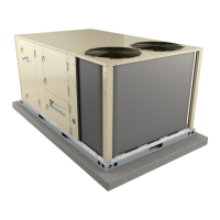
STANDARD HEAT (130,000BTUH)
INSERTS (2)
INSERTS (4)
HIGH HEAT (180,000BTUH)
Note - No inserts on
medium heat.
INSERT LOCATION - DIRECT DRIVE ONLY
FIGURE 27
FIGURE 28
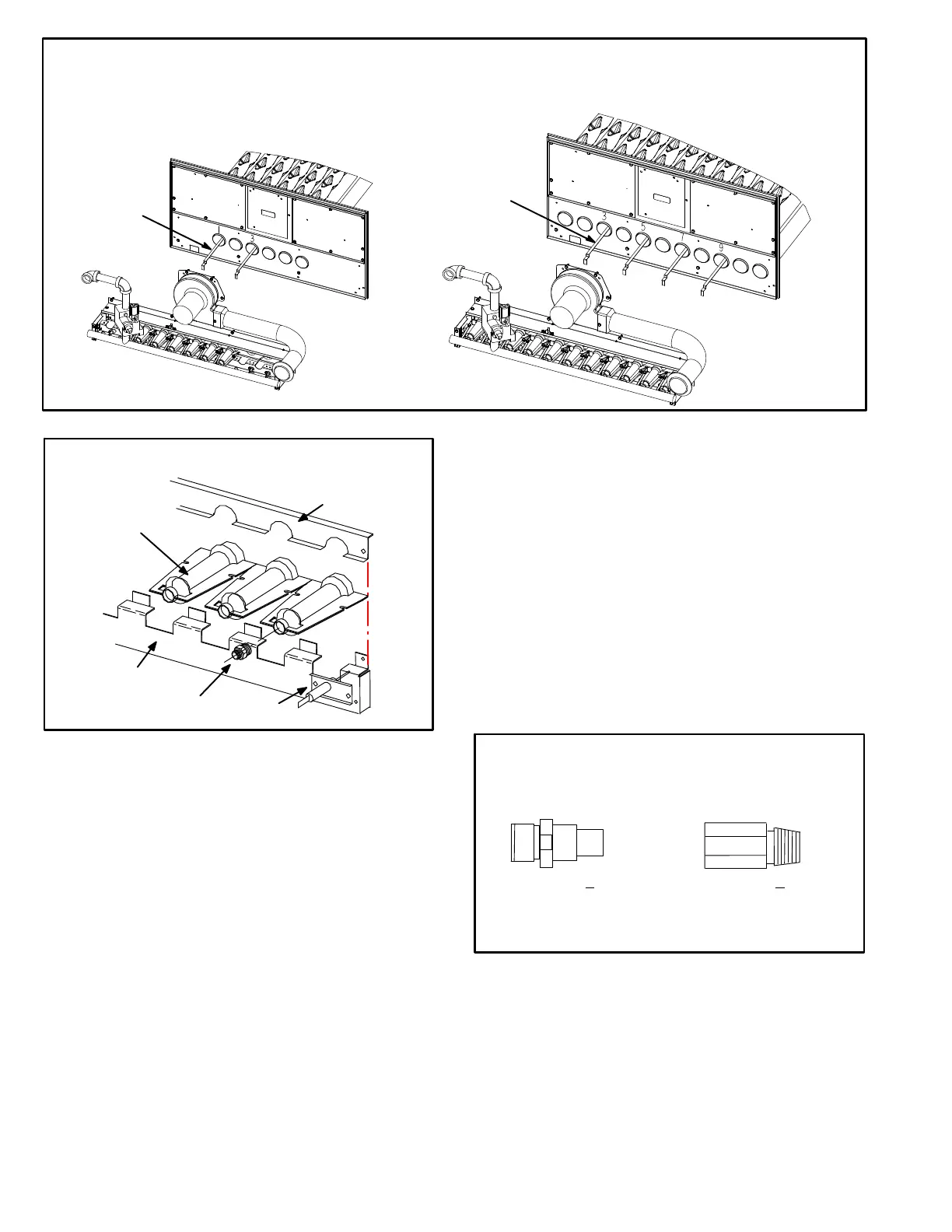
TYPICAL GAS BURNER ASSEMBLY
BURNERS
ORIFICE
SENSOR
BURNER
SUPPORT
BURNER
SUPPORT CAP
Orifice
Each burner uses an orifice (two types figure 29) which is
precisely matched to the burner input. Install only the
orifices with the same threads. The orifice is threaded
into the burner manifold. The burner is supported by the
orifice and will easily slide off for service.
NOTE-Do not use thread sealing compound on the
orifices. Using thread sealing compound may plug
the orifices.
Each orifice and burner are sized specifically to the unit.
Refer to ProductZone@www.davenet.com for correct siz
ing information.
5-Primary High Temperature Limits S10
S10 is the primary high temperature limit and is located on the
blower deck to the right of the blower housing.
Primary limit S10 is wired to the A55 Unit Controller which
energizes burner 1 control (A3). Its N.C. contacts open to
de-energize the ignition control when excessive tempera
ture is reached in the blower compartment. At the same
time, the N.O. contacts of S10 close energizing the blower
relay coil K3 through A55. If the limit trips the blower will be
energized. Limit settings are factory set and cannot be ad
justed. If limit must be replaced, the same type and set point
must be used.
ORIFICE WITH
PIPE THREADS
Tighten to 6.25 + .5 ft.lbs.
Do not over-tighten.
Tighten to 14 + .5 ft/lbs
Do not over-tighten.
ORIFICE WITH
STRAIGHT THREADS
FIGURE 29
 Loading...