EasyManuals Logo
Home>Lennox>Air Handlers>LGT Series

Lennox LGT Series User Manual

Lennox LGT Series
61 pages
To Next Page IconTo Next Page
To Previous Page IconTo Previous Page
Page #14 background imageLoading...
Page #14 background image
Page 14
I-UNIT COMPONENTS
WARNING
Electric shock hazard. Can cause injury
or death. Before attempting to perform
any service or maintenance, turn the
electrical power to unit OFF at disconnect
switch(es). Unit may have multiple power
supplies.
ELECTROSTATIC DISCHARGE (ESD)
Precautions and Procedures
CAUTION
   󰀨
electronic components. Take precautions
to neutralize electrostatic charge by
touching your hand and tools to metal
prior to handling the control.





A-Control Box Components

control box is located in the upper portion of the compres-
sor compartment.
1-Disconnect Switch S48 (Optional)
All units may be equipped with an optional disconnect


-
cian to disconnect power to the unit.
2-Control Transformer T43 (Re-Heat Units)
T43 is a single line voltage to 24VAC and ties into T1.
See unit diagram. T43 is mounted in the control box. The
transformer supplies power to control circuits (through




single primary voltage tap.
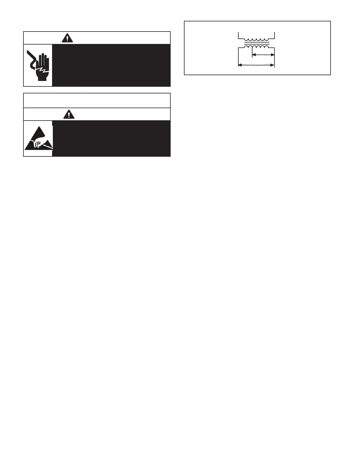
3-Control Transformer T1
All use a single line voltage to 24VAC transformer mount-
ed in the control box. Transformer supplies power to con-
trol circuits in the unit. The transformer is rated at 92VA
and is protected by a 6 amp circuit breaker (CB8). The
      
-
age transformers use a single primary voltage tap.
BLUE YELLOW
ORANGE
RED
BLACK
230 VOLTS
208 VOLTS
PRIMARY
SECONDARY
208/230V TRANSFORMER
FIGURE 3
4-Outdoor Fan Relay K10, K68

󰀩

5-Outdoor Fan Capacitors C1, C2

         
with unit tonnage and voltage.




6-C. A. I. Transformers T3 575V Units


         
       
blower motor (B6).
7-Compressor Contactor K1, K2
     
contactors with 24VAC coils. K1 and K2 (both energized

8-Burner Controls A3
A3 controls gas heat section burner controls. Burner con-
trols are factory set and are not adjustable. The control
makes three attempts at ignition and then locks out the
system if ignition is not obtained after the third trial. Reset
after lockout requires only breaking and remaking thermo-
󰀨
in the event of a gas or power failure. Upon restoration
  -

         

9-Power Exhaust Relay K65 (PED units)
          
          


       


Questions and Answers:

Question and Answer IconNeed help?

Do you have a question about the Lennox LGT Series and is the answer not in the manual?

Lennox LGT Series Specifications

General IconGeneral
BrandLennox
ModelLGT Series
CategoryAir Handlers
LanguageEnglish

Related product manuals