Page 39
VII-ACCESSORIES
The accessories section describes the application of most
installed to the LGT units.
A-Mounting Frames
When installing units on a combustible surface for down-
frame is used. The roof mounting frames are recommend-
ed in all other applications but not required. If the LGT
be supported under all edges and under the middle of the
unit to prevent sagging. The units MUST be mounted level
-
tion.
-
-
structions for details of proper assembly and mounting.
The roof mounting frame MUST be squared to the roof
and level before mounting. Plenum system MUST be in-
stalled before the unit is set on the mounting frame. Typ-
-
fer to the roof mounting frame installation instructions for
proper plenum construction and attachment.
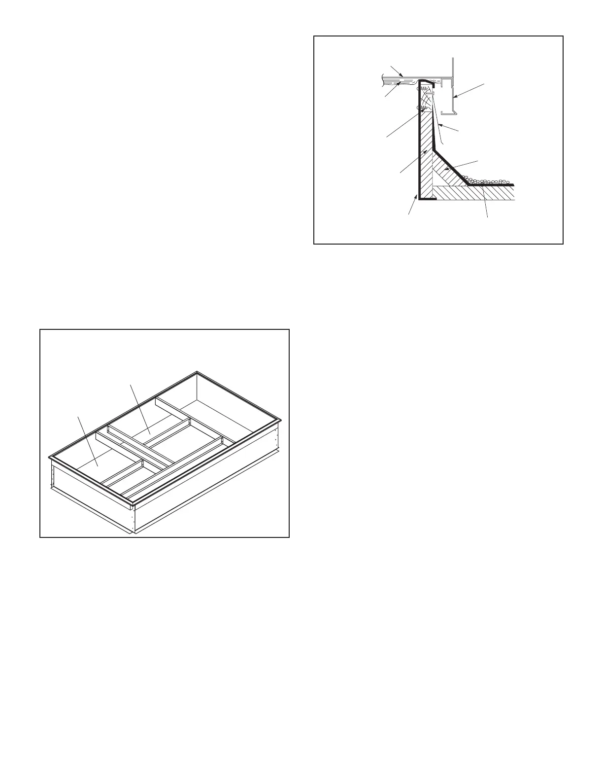
ASSEMBLED ROOF MOUNTING FRAME
SUPPLY AIR
OPENING
RETURN AIR
OPENING
FIGURE 27
B-LP / Propane Kit
Natural to LP /propane kit includes a spring kit and three
to LP gas changeover kit installation instructions.
C-Dirty Filter Switch S27
-
-
es at 1” W.C. (248.6 Pa) The switch is mounted on the
is shown on the temperature control section (C2) wiring
diagram in back of this manual.
ROOF
MOUNTING FRAME
(Extends around entire
perimeter of unit)
FIBERGLASS
INSULATION
(Furnished)
COUNTER FLASHING
(Field Supplied)
UNIT BASE
BOTTOM
RIGID INSULATION
(Field Supplied)
ROOFING
MATERIAL
CANT STRIP
(Field Supplied)
NAILER STRIP
(Furnished)
UNIT BASE
RAIL
TYPICAL FLASHING DETAIL
FIGURE 28
D-Transitions
-
-
tion must be installed in the C1CURB mounting frame be-
fore mounting the unit to the frame. Refer to the manufac-
turer’s instructions included with the transition for detailed
installation procedures.
E-LAOAD(M) Outdoor Air Dampers (all units)
LAOAD(M) consists of a set of dampers which may be
-
be cleaned with water and a mild detergent. It should be
-
lation.
LGT units. Refer to manufacturer’s instructions included
with transition for detailed installation procedures.
G-Blower Proving Switch S52
The blower proving switch monitors blower operation and
locks out the unit in case of blower failure. The switch
is N.O. and closes at .14” W.C. (34.9 Pa) The switch is
mounted on the upper left hand corner of the blower deck.
Wiring for the blower proving switch is shown on the tem-
perature control section (C2) wiring diagram in back of this
manual.

 Loading...