Page 34
IV-START-UP - OPERATION
Refer to start-up directions and to the unit wiring diagram
when servicing. See unit nameplate for minimum circuit
ampacity and maximum fuse size.
A-Preliminary and Seasonal Checks
1 - Make sure the unit is installed in accordance with
the installation instructions and applicable codes.
2 -
installed for loose connections. Tighten as required.
Refer to unit diagram located on inside of unit
control box cover.
3 - Check to ensure that refrigerant lines are in good
condition and do not rub against the cabinet or
other refrigerant lines.
4 - Check voltage. Voltage must be within the range
company and have the voltage corrected before
starting the unit.
Recheck voltage and amp draw with unit running. If
stop unit and consult power company. Refer to unit
nameplate for maximum rated load amps.
6 - Inspect and adjust blower belt (see section on
Blower Compartment - Blower Belt Adjustment).
NOTE-Crankcase heaters must be energized 24 hours
before attempting to start compressor. Set thermostat so
that there is no demand to prevent compressor from cy-
cling. Apply power to unit.
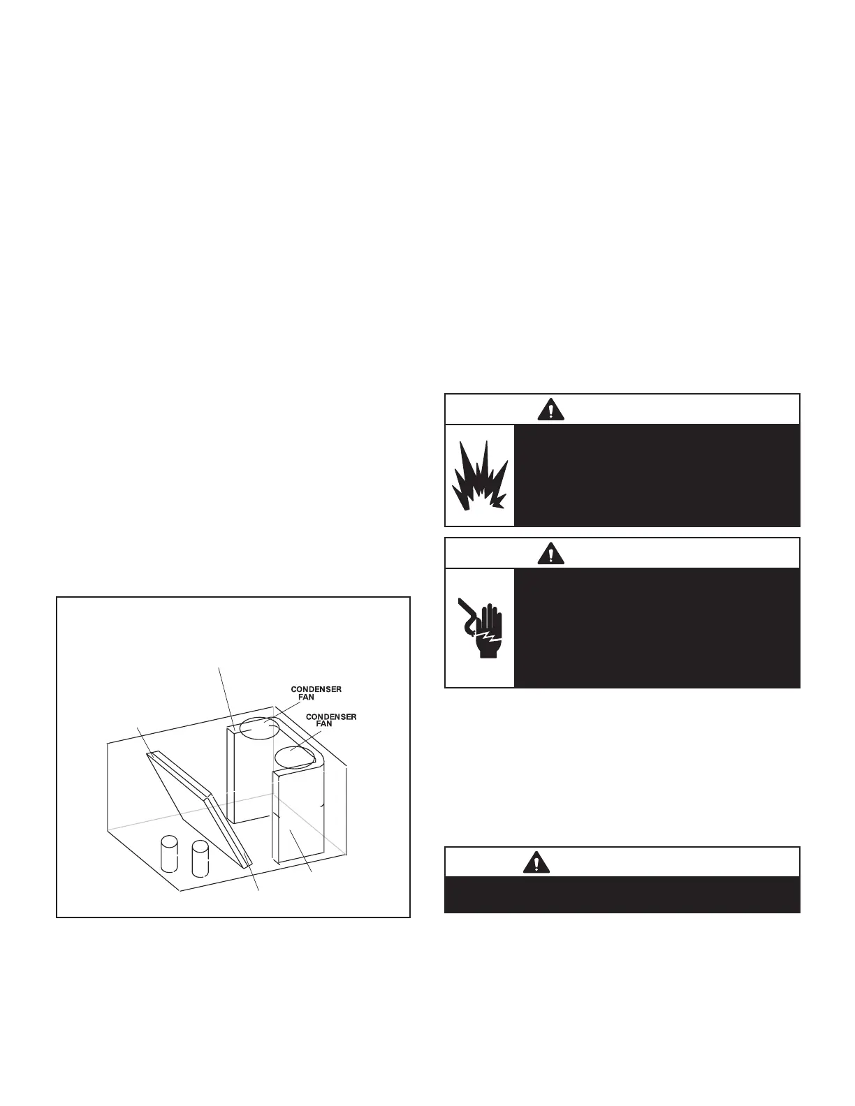
REFRIGERANT STAGES -
All-Aluminum Coil
1
2
(BOTH FANS ARE ENERGIZED
WITH A Y1 DEMAND)
CONDENSER COIL
STAGE 1
EVAPORATOR
COIL STAGE 1
EVAPORATOR
COIL STAGE 2
CONDENSER COIL
STAGE 2
B4
B5
FIGURE 23
1 -
according to instructions provided with thermostat.
2 -
thermostat demand will energize compressor 1
energize compressor 2.
-
mostat demand will energize compressor 1 Part Load.
Second-stage thermostat demand will energize com-
pressor 2.
Third-stage thermostat demand will energize compres-
3 - Units contain two refrigerant circuits or stages.
4 - Each refrigerant circuit is separately charged with
refrigerant. See unit rating plate for correct amount
of charge.
C-Heating Start-up
FOR YOUR SAFETY READ BEFORE LIGHTING
WARNING
Danger of explosion. Can cause injury
or product or property damage. If
overheating occurs or if gas supply
electrical supply.
WARNING
Electric shock hazard. Can cause injury
or death. Do not use this unit if any part
has been under water. Immediately call a
unit and to replace any part of the control
system and any gas control which has
been under water.
Use only your hand to push in or turn the gas control knob.
Never use tools. If the knob will not push in or turn by
-
explosion.
IMPORTANT
Units equipped with a Hot Gas Reheat system MUST
be charged in standard cooling mode.
ignition control.

 Loading...