13
hours,thentheincrementbecomesonehour.
6.5.7. Timer OFF Operation
1. Pressthe Timer OFF button. The TimerOFF icon, the
lastauto-offtime,and“h”willdisplay.
2. PresstheTimer OFFbuttonagaintosettheamountof
timebeforetheindoorunitstopsoperation.Eachpress
will increase the time in half hour increments until 10
hours,thentheincrementbecomes1hour.
6.5.8. Modify Timer ON/OFF settings
1. Press either the Timer ON button or the Timer OFF
buttontomodifythatsetting.
2. Usetheuparrowanddownarrowbuttonstochangethe
timedoperationintervals.
3. Setthetimerto0.0toturnofftimedoperation.
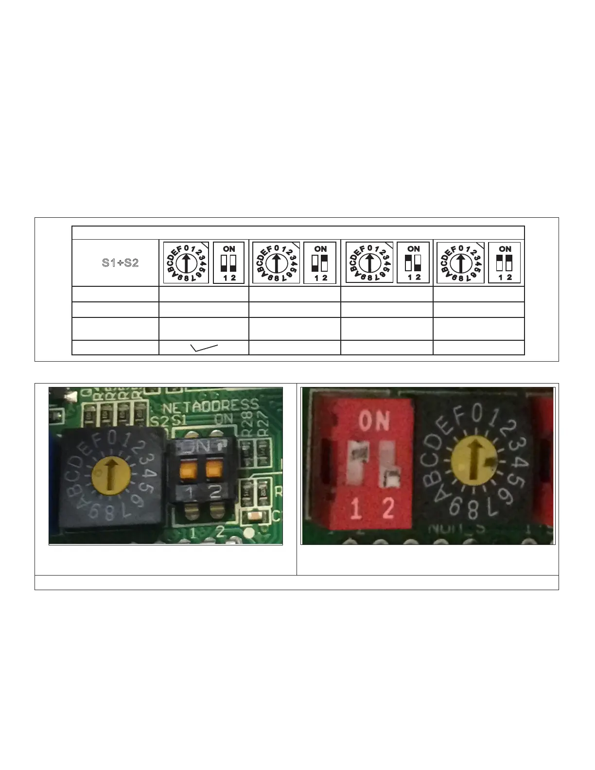
7. Connection to Centralized Controller
7.1. Set Indoor Unit Address for Centralized
Control (Used with VRF Only)
All indoor units connected to a centralized controller must
haveauniqueaddress.UsetheS1dipswitchandtheS2
dialswitchtosettheaddressforeachindoorunit.Thetable
belowshowshowtosettheuniqueaddresses.
Allindoorunitsarefactorysetto“0”.Tochangetheaddress
to“1”,movethedialswitchtothe1position,donotadjust
thedipswitches.Tochangetheaddressto“35”,movedip
switch1totheUPpositionandmovethedialswitchtothe
3 position.
0
8
4
1
2
3
5
6
7
C
9
A
B
D
E
F
1
2
ON
0
8
4
1
2
3
5
6
7
C
9
A
B
D
E
F
1
2
ON
0
8
4
1
2
3
5
6
7
C
9
A
B
D
E
F
1
2
ON
0
8
4
1
2
3
5
6
7
C
9
A
B
D
E
F
1
2
ON
S1+S2
FOR SETTING ADDRESS
RANGE
ADDRESS
FACTORY SETTING
0 ~ F 0 ~ F 0 ~ F 0 ~ F
0 ~ 15 16 ~ 31 32 ~ 47 48 ~ 63
DIP SWITCH
HANDLES
LEFT - DOWN
RIGHT - DOWN
LEFT - DOWN
RIGHT - UP
LEFT - UP
RIGHT - DOWN
LEFT - UP
RIGHT - UP
Figure 13. Dip Switches
Indoor Unit Address is 0
BothdipswitchhandlesareDOWN,dialpointsto0.
Indoor Unit Address is 32
Dipswitch1isUPanddipswitch2isDOWN,dialpointsto0.
Switchlocationandcolorvariesforeachindoorunit.Twoexamplesareshownabove.
Figure 14. Dip Switch Settings
 Loading...