14
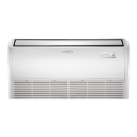
7.2. Indoor Unit Connection Points for
Centralized Controller
Mini-split indoor units can be connected to a centralized
controller(e.g.LennoxVRFManager-LVMorTraneTracer)
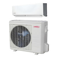
oraBACnetorLonWorksgatewayusingtheXYEterminals
ontheindoorunitmainboard.
Figure 15. Indoor Unit Connection Points
(Typical Wiring Diagram)
Figure 16. Typical Indoor Unit Connection Points
7.3. Dry Mode Operation - Indoor Units
7.3.1. Procedure
1. PresstheMODEbuttontoselectDRY mode.
2. Press the UP/ DOWN button to select the desired
temperature.Thetemperaturesettingrangeisfrom62°F
to86°Finonedegreeincrements.
NOTE: The blower is preset at a low speed and cannot be
changed therefore it will get cold and most likely
will over shoot the temperature setting by 6-10
degrees depending on the room size or other
various factors. Also the Follow Me mode does
not operate in this mode. The Follow Me mode is
only available when a return air sensor is utilized.
Typically in most cases the Follow Me mode will
not be sufcient to remove excessive humidity.
NOTE: In addition, the outdoor units do not have a
humidistat installed therefore they are unable to
determine humidity levels. This product is not
recommend as a main source for dehumidication.
Note, this well over shoot the temperature by 6-8
degrees below what was set for dry mode.
NOTE: Using this mode will over shoot the temp by 6-8
degrees below what was set for dry mode.
7.3.2. Dry Mode Operation Sequence
Whenindrymodeoperation the unit is actually in cooling
modewithalow speedbloweroperation.Thecompressor
willstopwhentheroomtemperatureistwodegreesCelsius
lowerthanthetemperaturesetting.
However there is a temperature compensation for cooling
modethatistwodegreesCelsius.Sotheunitwillstopwhen
thetemperatureisfourdegreesCelsiuslowerthantheroom
temperaturesettings.
NOTE: Four degrees Celsius is equivalent to 8°F
difference.
7.4. Test Run - Indoor Units
Onlyperformtestrunafteryouhavecompletedthefollowing
steps:
• ElectricalSafetyChecks–Conrmthattheunit’s
electricalsystemissafeandoperatingproperly
• GasLeakChecks–Checkallarenutconnectionsand
conrmthatthesystemisnotleaking
• Conrmthatgasandliquid(highandlowpressure)
valvesarefullyopen.
7.4.1. Test Run Instructions
YoushouldperformtheTestRunforatleast30minutes.
1. Connectpowertotheunit.
2. PresstheON/OFFbuttonontheremotecontrollertoturn
it on.
3. Press the mode button to scroll through the functions,
oneatatime:
4. Leteach functionrunfor ve minutes, and performthe
followingchecks:
7.4.2. Before Test Run
Table 3. Test Run Checklist
Checks Pass Fail
Noelectricalleakage
Unitisproperlygrounded
Allelectricalterminals
properlycovered
Indoorandoutdoorunits
aresolidlyinstalled
Allpipeconnectionpoints
donotleak
Waterdrainsproperlyfrom
drainhose
Allpipingisproperly
insulated
UnitperformsCOOL
functionproperly
Indoorunitlouversrotate
properly
Indoor unit responds to
remotecontroller
 Loading...