27
13.7.2. Refrigerant Charging
• Connectthechargehosetothechargingcylinder,open
thetwo-wayvalveandthethree-wayvalve.
• Connectthechargehosewhichyoudisconnectedfrom
thevacuumpumptothevalveatthebottomofthe
cylinder.IftherefrigerantisR-410A,makethecylinder
bottomuptoensureliquidcharge.
• Purgetheairfromthechargehose
• Openthevalveatthebottomofthecylinderandpress
thecheckvalveonthechargesettopurgetheair(be
carefuloftheliquidrefrigerant).
• Putthechargingcylinderontotheelectronicscaleand
recordtheweight.
• Openthevalves(Lowside)onthechargesetand
chargethesystemwithliquidrefrigerant.Ifthe
systemcannotbechargewiththespeciedamount
ofrefrigerant,orcanbechargedwithalittleatatime
(approximately150geachtime),operatingtheair
conditionerinthecoolingcycle;however,onetimeis
notsufcient,waitapproximately1minuteandthen
repeattheprocedure.
• Whentheelectronicscaledisplaystheproperweight,
disconnectthechargehosefromthe3-wayvalve’s
serviceportimmediately
• Ifthesystemhasbeenchargedwithliquidrefrigerant
whileoperatingtheairconditioner,turnofftheair
conditionerbeforedisconnectingthehose.
• Mountedthevalvestemcapsandtheserviceport.
Usetorquewrenchtotightentheserviceportcaptoa
torqueof18N·m(13.27ft·lbs).
• Alwaysleakcheckafterservicingtherefrigerant
system.
Thereareonelow-pressurecentralizedvalveandonehigh-
pressurecentralizedvalve,itwillbemoretimesavingwhen
vacuum and recycle refrigerant. But refer to the previous
instructionwhenvacuumandrecyclerefrigerant.
14. Electronic Function
14.1. Abbreviation
• T1:Indoorambienttemperature
• T2:Middleindoorheatexchangercoiltemperature
• T3:Outdoorheatexchangerpipetemperature
• T4:Outdoorambienttemperature
• T5:Compressordischargetemperature
14.2. Electric Control Working
Environment.
• Inputvoltage:230V.
• Inputpowerfrequency:60Hz.
• Indoorfanstandardworkingamp.:<1A
• Outdoorfanstandardworkingamp.:<1.5A.
• Four-wayvalvestandardamp.:<1A
15. Adding Refrigerant - Single-Zone Systems
Theoutdoorunitisfactory-chargedwithrefrigerant.Calculate
theadditionalrefrigerantrequiredaccordingtothediameter
and the lengthof the liquid pipe between the outdoor unit
andindoorunitconnections.
Besuretoaddtheproperamountofadditionalrefrigerant.
Failuretodosomayresultinreducedperformance.
See “Table 4. Line Set Guide” on page 23 for how much
refrigerantneedstobeaddedbasedonpipelength.
NOTE: Interconnecting pipe work between outdoor and
indoor units must be 10 ft. or longer.
NOTE: Do not remove refrigerant for line lengths less
than 25 ft. R-410A is a blended refrigerant. If you
must remove charge, it is necessary to remove
the entire charge and weigh in the new charge.
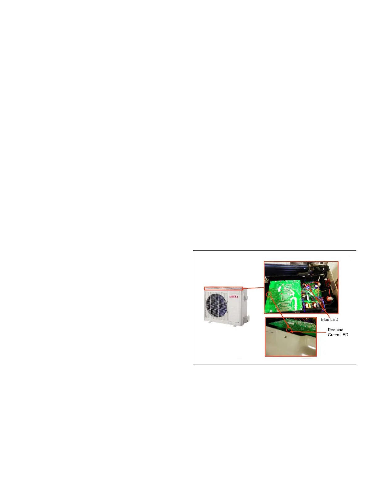
16. Single-Zone Outdoor Unit LED Locations
Single-zoneoutdoor units displayashcodeson the main
board.Themain boardisaccessed throughthetop ofthe
unit.Indoorunitswilldisplaymoredetailederrorcodes.
These outdoor units do not have a SW1 spot check push
button switch. Diagnostic isperformed through a seriesof
blue,redandgreenLEDs.
NOTE: The control on all single-zone outdoor units is
mounted with all LEDs down and cannot be seen
unless the control is removed.
Figure 25. Typical Location of Outdoor Unit LEDs
 Loading...