Page 10
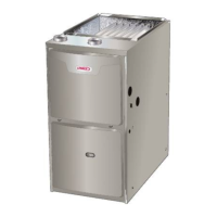
FIGURE 6
Primary Limit Location and Heat Exchanger
Install limit face down
4. Gas Valve (GV1)
The ML196DFE uses an internally redundant to valve to as
sure safety shut‐off. If the gas valve must be replaced, the
same type valve must be used.
24VAC terminals and gas control switch are located on
top of the valve. All terminals on the gas valve are con
nected to wires from the ignition control. 24V applied to the
terminals opens the valve.
Inlet and outlet pressure taps are located on the valve. A
manifold adjustment screw is also located on the valve. An
LP/Propane changeover kit is available.
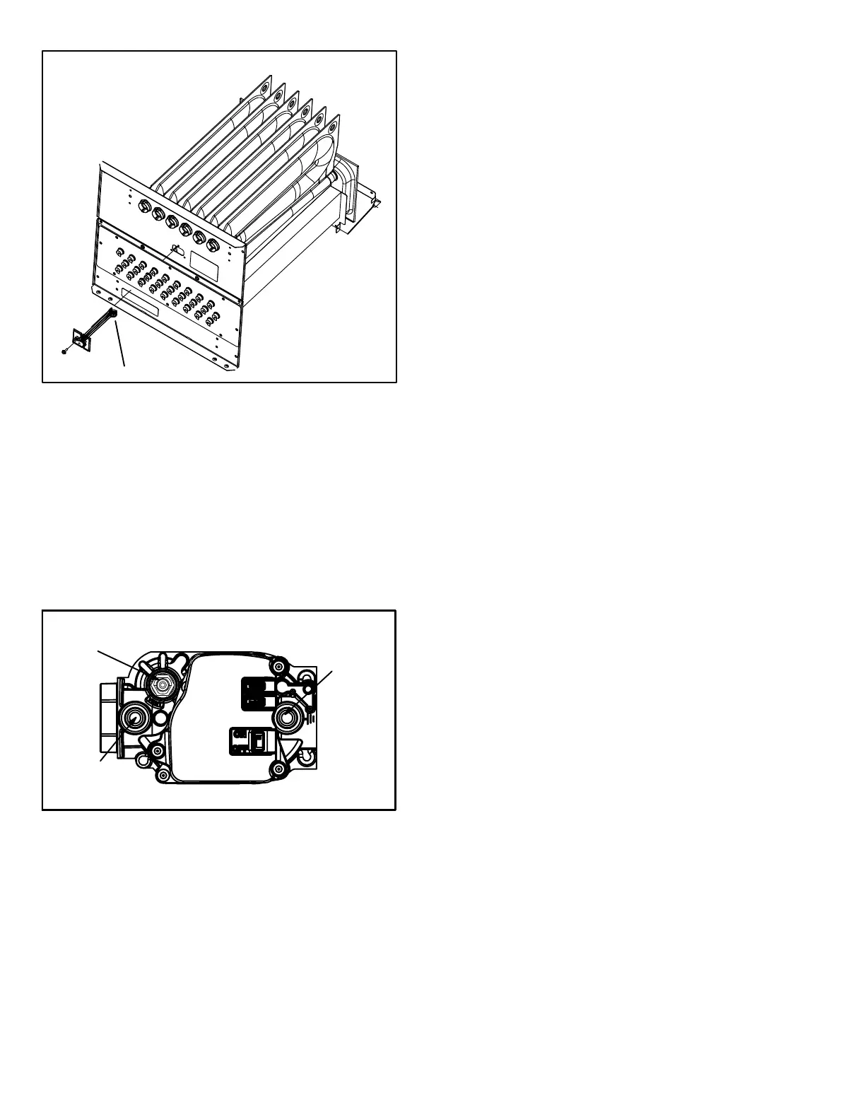
FIGURE 7
GAS VALVE SHOWN IN ON POSITION
MANIFOLD
PRESSURE
OUTLET
PORT
INLET
PRESSURE
PORT
MANIFOLD PRESSURE
ADJUSTMENT SCREW
(under barbed fitting)
5. Flame Sensor (Figure 5)
A flame sensor is located on the left side of the burner sup
port. The sensor is mounted on the bottom burner box plate
and the tip protrudes into the flame envelope of the left-
most burner. The sensor can be removed for service with
out removing any part of the burners. During operation,
flame is sensed by current passed through the flame and
sensing electrode. The ignition control allows the gas valve
to remain open as long as flame signal is sensed.
NOTE - The ML196DFE is polarity sensitive. Make sure
that the furnace is wired correctly and is properly grounded.
A microamp DC meter is needed to check the flame signal
on the integrated control.
Flame (microamp) signal is an electrical current which passes
from the integrated control to the sensor during unit operation.
Current passes from the sensor through the flame to ground to
complete a safety circuit.
To Measure Flame Signal - Integrated Control:
Use a digital readout meter capable of reading DC micro
amps. See figure 8 for flame signal check.
1 - Set the meter to the DC amps scale.
2 - Turn off supply voltage to control.
3 - Remove sensor wire from integrated control.
4 - Connect (-) lead to flame sensor wire.
5 - Connect (+) lead to Terminal FS on integrated control.
6 - Turn supply voltage on and close thermostat contacts to
cycle system.
7 - When main burners are in operation for two minutes, take
reading.
6. Ignitor (Figure 5)
ML196DFE units use a mini-nitride ignitor made from a pro
prietary ceramic material. To check ignitor, measure its re
sistance and voltage. A value of 39 to 70 ohms indicates a
good ignitor. Voltage to the ignitor should be 102VAC -
132VAC. See figure 9 for resistance and voltage checks.
 Loading...