Page 9
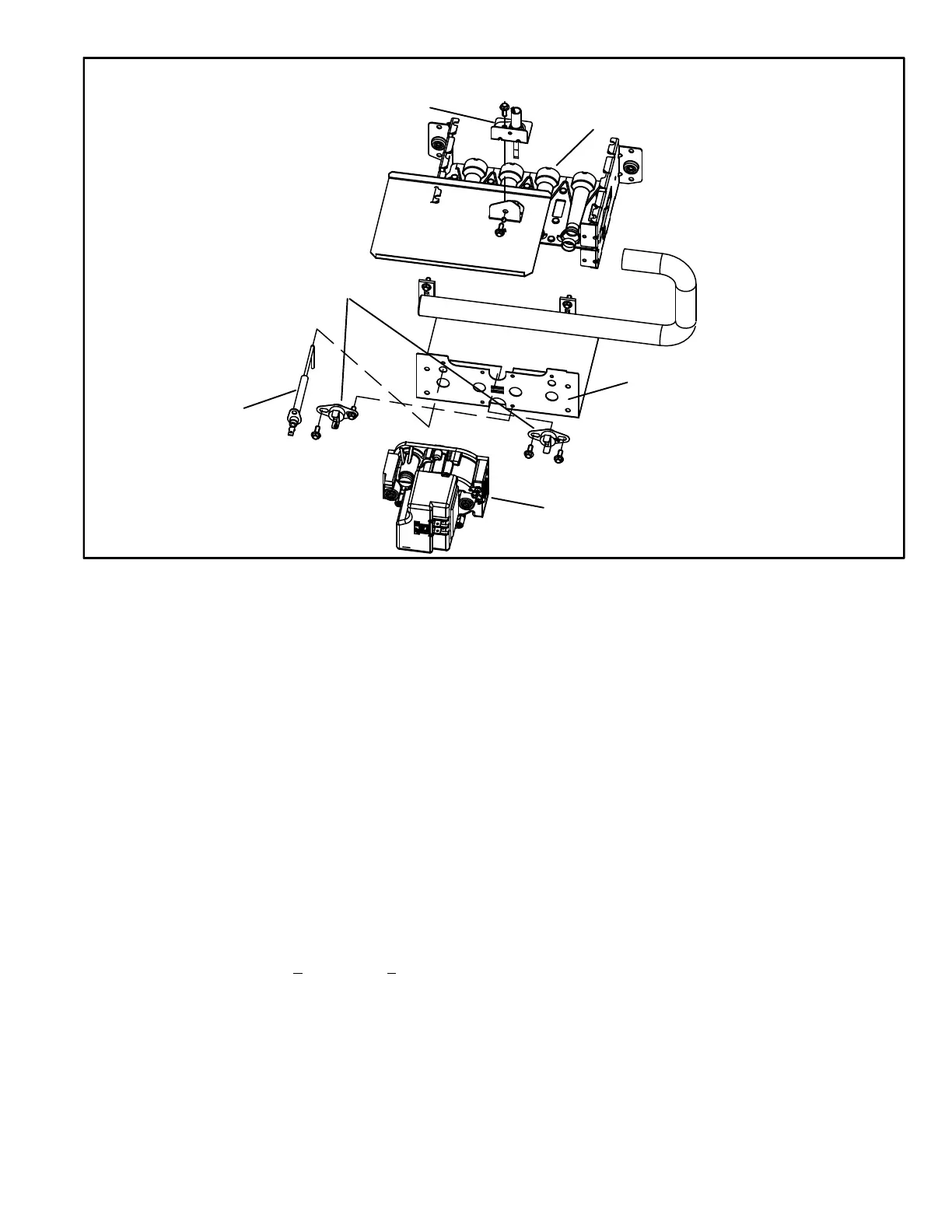
FIGURE 5
ML196DFE Burner Box Assembly
SENSOR
ROLLOUT SWITCHES
GAS VALVE
IGNITOR
BURNERS
FRONT BURNER BOX PLATE
B-Heating Components
Combustion air inducer (B6), primary limit control (S10),
SureLight ignitor, burners, flame rollout switch (S47), gas
valve (GV1), combustion air prove switch (S18), and clam
shell heat exchangers are located in the heating compart
ment. The heating compartment can be accessed by re
moving the outer access panel.
1. Flame Rollout Switches (Figure 5)
Flame rollout switches S47 are SPST N.C. high temperature
limits located on the top left and bottom right of the front buner
box plate. S47 is wired to the burner ignition control A92.
When either of the switches sense flame rollout (indicat
ing a blockage in the combustion passages), the flame
rollout switch trips, and the ignition control immediately
closes the gas valve. Switch S47 in all ML196DFE units is
factory preset to open at 210_F +
12_F (99_C + 6.7_C) on a
temperature rise. All flame rollout switches are manual reset.
See table 4 flash code 8 for troubleshooting.
2. Heat Exchanger (Figure 6)
ML196DFE units use an aluminized steel primary and
stainless steel secondary heat exchanger assembly.
Heat is transferred to the air stream from all surfaces of
the heat exchanger. The shape of the heat exchanger en
sures maximum efficiency.
The combustion air inducer pulls fresh air through the burn
er box. This air is mixed with gas in the burners. The gas /
air mixture is then burned at the entrance of each clam
shell. Combustion gases are then pulled through the primary
and secondary heat exchangers and exhausted out the ex
haust vent pipe.
3. Primary Limit Control (Figure 6)
Primary limit (S10) used on ML196DFE units is located in the
heating vestibule panel. When excess heat is sensed in the
heat exchanger, the limit will open. Once the limit opens, the
furnace control energizes the supply air blower and de-en
ergizes the gas valve. The limit automatically resets when
unit temperature returns to normal. The switch is factory
set and cannot be adjusted. For limit replacement remove
wires from limit terminals and rotate limit switch 90 de
grees. Slowly remove from the vestibule panel. Install re
placement limit with same care.
 Loading...