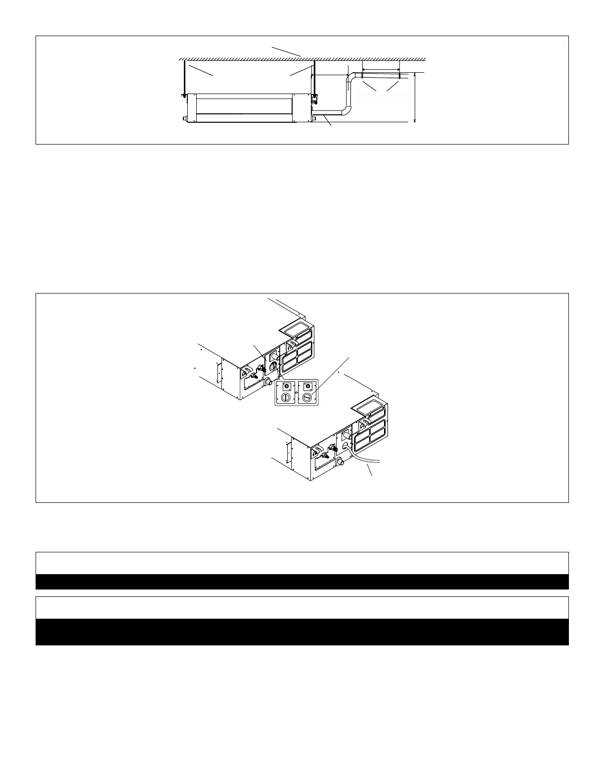
80
SUSPENSION RODS
DRAIN LINE
STRUCTURAL CEILING
8 in.
(203 mm)
Max. 28 in.
SUPPORT
STRAPS
3 ft. (1 m)
Figure 54. Condensate Drain with Pump
5. After system installation is complete, the condensate drain line must be checked for leaks and the condensate
pumps must be checked to ensure proper operation. This check is part of the start-up process which must be
done by the installing contractor. Turnthecondensatedrainpantestcoverlatchcounterclockwisetoopenthecover
andaccessthedrainpan. Seegurebelow.Funnelenoughwatertoengagethepumpintothe drainpanthrougha
exibletube.
6. Operatethesysteminthecoolingmode.Iftheinternalpumpisbeingused,ensurethatthepumpisoperatingandthe
waterinthepanisdrainingfreely.Iftheinternalpumpisnotbeingused,pourthewaterintothedrainpanandconrm
thatithasowedfreelyoutofthepanandoutofthedraintermination.Ifaleakisfound,shutdownpowertotheunitat
onceanddonotrestorepowertotheunituntiltheproblemhasbeenresolved.
7. Returnthetestcoverandturnthelatchclockwisetore-lockit.
DRAIN PAN
TEST COVER
FUNNEL WATER INTO
PAN THROUGH TUBE
FOR TEST
COVER LATCH
(Turn latch
counterclockwise
to unlock)
CL
OSE
D
O
PE
N
CLOS
E
D
O
PE
N
Figure 55. Condensate Drain Test
14.3.1.2 M22A, M33A and M33B
CAUTION
Makesurethatdrainpipingisproperlyroutedandinsulatedinordertopreventbothleaksandcondensation.
IMPORTANT
Drainshouldhaveaslopeofatleast¼inchperfootandshouldbeapprovedcorrosion-resistantpipe.Youmustconrm
operationofeverydrainandpumpinthesystemaspartofthecommissioningprocedure.
1. Useaeld-providedhoseclamptosecurethedrainlinestubonthesideofthecassettebasetoaeld-supplied1”(25
mm) drain line.
NOTE: Take care not to over-tighten the hose clamp as this may damage the drain line stub.
2. Seegurebelowforapplicationsusingtheunit’sinternalcondensatepumptoprovideliftintoadrain.Ensurethatthe
maindrainlineisproperlysloped(nolessthan1/4inchperfoot(18mmperm)).
3. Drainshouldbeasshortaspossibleandshouldnothaveanydroopsorkinksthatwouldrestrictcondensateowand
shallbeapprovedresistantpipe.
 Loading...