EasyManuals Logo
Home>Lennox>Air Conditioner>MPC

Lennox MPC User Manual

Lennox MPC
104 pages
To Next Page IconTo Next Page
To Previous Page IconTo Previous Page
Page #67 background imageLoading...
Page #67 background image
67
11.5. MPC Five-Zone Refrigerant Cycle Diagram
LIQUID VALVE A
GAS VALVE A
Indoor Coil Outdoor Coil
COOLING
HEATING
T2 Evaporator
temp. sensor
T1 Room
temp. sensor
T3
Condenser
temp. sensor
T4 Ambient
temp. sensor
INDOOR OUTDOOR
EXV A
CAPILIARY A
CHECK VALVE
CAPILIARY TUBE
EXV B
CAPILIARY B
LIQUID VALVE B
GAS VALVE B
EXV C
CAPILIARY C
LIQUID VALVE C
GAS VALVE C
EXV D
CAPILIARY D
LIQUID VALVE D
GAS VALVE D
EXV E
CAPILIARY E
LIQUID VALVE E
GAS VALVE E
Compressor
4-WAY VALVE
T5 Discharge
temp. sensor
Accumulator
High pressure
switch
Low pressure
switch
11.6. MLB Six-Zone Refrigerant Cycle Diagram
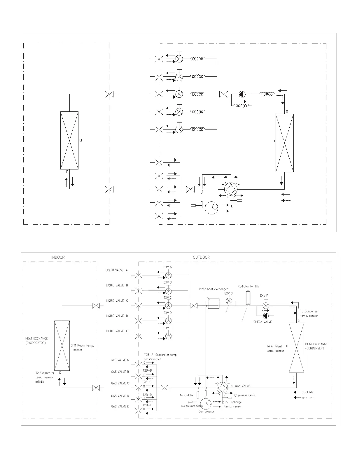
This plate heat exchanger is to
cool the gas for compressor
during heating mode.
This EXV G, only open during the heating
mode and at low ambient temperature.
The Radiator is to cool the PCB at heating and cooling mode
Radiator is to cool the PCB at heating and cooling mode
The Radiator is to cool the PCB at heating and cooling mode

Table of Contents

Questions and Answers:

Question and Answer IconNeed help?

Do you have a question about the Lennox MPC and is the answer not in the manual?

Lennox MPC Specifications

General IconGeneral
BrandLennox
ModelMPC
CategoryAir Conditioner
LanguageEnglish

Related product manuals