7
NOTE: DIAGRAMS & ILLUSTRATIONS ARE NOT TO SCALE.
LENNOX HEARTH PRODUCTS • MERIT PLUS
®
DIRECT VENT GAS FIREPLACES (MPD33/35/40/45) • CARE AND OPERATION INSTRUCTIONS
NOTICE: A white fi lm may develop
on the glass enclosure panel during
the fi rst few fi res as part of the burn-in
process.
The first few times you use the
fi replace, clean the glass after each use
(AFTER THE GLASS HAS COMPLETELY
COOLED); otherwise, the white fi lm
will bake onto the glass and become
diffi cult to remove.
See glass cleaning instructions on
Page 10.
Fuel # Low High
Natural
Gas
1.6 in. WC
(0.40 kPa)
3.5 in. WC
(0.87 kPa)
Propane
6.3 in. WC
(1.57 kPa)
10.0 in. WC
(2.49 kPa)
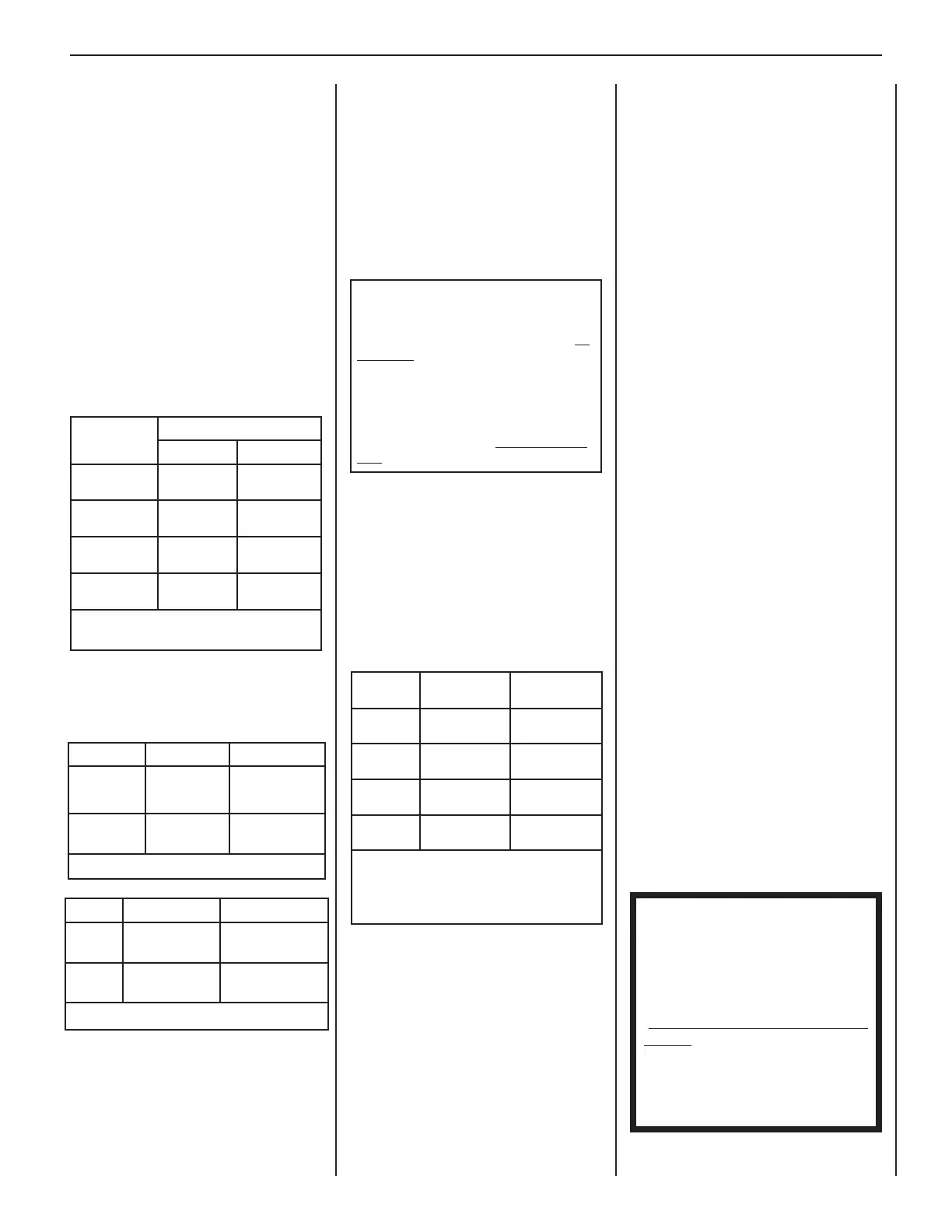
Table 3: Manifold Gas Supply Pressure
GENERAL INFORMATION
(continued)
BTU Input
Millivolt appliances are manually controlled
and feature a spark igniter (piezo) that allows
the appliance pilot gas to be lit without the
use of matches or batteries. This system
provides continued service in the event of a
power outage.
Millivolt models come standard with a
manually-modulated gas valve. Flame
appearance and heat output can be controlled
at the gas valve.
Both millivolt and electronic systems can be
operated during a power outage, and feature
manually operated hi-low fl ame control. The
BTU Input for these appliances is shown in
Table 1.
Burn-in Period
During the fi rst few fi res of this appliance
there will be some odor due to the curing of
the paint and burning off of lubricants used
in the manufacturing process. Depending on
your use, the burn-in period may take a few
hours or a few days.
KEEP YOUR HOUSE WELL VENTILATED
DURING THE CURING PROCESS. THE ODOR
AND HAZE EMITTED DURING THE CURING
PROCESS CAN BE QUITE NOTICEABLE AND
MAY SET OFF A SMOKE DETECTOR.
If an optional blower is installed, do not turn
it on during the burn-in period.
Test gauge connections are provided on
the front of the millivolt and electronic gas
control valve (identifi ed IN for the inlet and
OUT for the manifold side). The control
valves have a 3/8 in. (10mm) NPT thread
inlet and outlet side of the valve (refer to
Figures 1 and 2).
Propane tanks are at pressures that will
cause damage to valve components. Verify
that the tanks have step down regulators to
reduce the pressure to safe levels.
Orifi ce Sizes—Sea Level to High Altitude
(All Models)
These appliances are tested and approved
for installation at elevations of 0-4500 feet
(0-1372 meters) above sea level using the
standard burner orifi ce sizes (marked with an
"*" in Table 4 ).
For elevations above 4500 feet, contact your
gas supplier or qualifi ed service technician.
The appliance and its appliance main gas
valve must be disconnected from the gas
supply piping system during any pressure
testing of that system at test pressures in
excess of 1/2 psi (3.5 kPa).
The appliance must be isolated from
the gas supply piping system by closing
its equipment shutoff valve during any
pressure testing of the gas supply piping
system at test pressures equal to or less
than 1/2 psi (3.5 kPa).
Fuel # Minimum Maximum
Natural
Gas
4.5 in. WC
(1.12 kPa)
10.5 in. WC
(2.61 kPa)
Propane
11.0 in. WC
(2.74 kPa)
13.0 in. WC
(3.23 kPa)
Table 2: Inlet Gas Supply Pressure
Gas Pressure—All Models
Tables 2 and 3 show the appliances' inlet and
manifold gas pressure requirements:
Deration—At higher elevations, the amount
of BTU fuel value delivered must be reduced
by either using gas that has been derated by
the gas company or by changing the burner
orifi ce to a smaller size as regulated by the
local authorities having jurisdiction and by
the (USA) National Fuel Gas Code NFPA 54—
latest edition / ANSI Z223.1-2009 or, in
Canada, the CAN/CSA-B149.1 codes—latest
edition.
Install the appliance according to the
regulations of the local authorities having
jurisdiction and, in the USA, the National
Fuel Gas Code NFPA 54—latest edition /
ANSI Z223.1-2009 or, in Canada, the CAN/
CSA-B149.1—latest edition.
Flame breadth, height and width will diminish
4% for every 1,000 feet of altitude.
In Canada - CAN/CGA-2.17-M91 (R2009)
(high altitude):
THE CONVERSION SHALL BE CARRIED
OUT BY A MANUFACTURER’S AUTHORIZED
REPRESENTATIVE, IN ACCORDANCE
WITH THE REQUIREMENTS OF THE
MANUFACTURER, PROVINCIAL OR
TERRITORIAL AUTHORITIES HAVING
JURISDICTION AND IN ACCORDANCE
WITH THE REQUIREMENTS OF THE
CAN/CGA-B149.1 OR CAN/CGA-B149.2
INSTALLATION CODES.
Models
Input Rate (BTU/HR)
Nat. Gas Prop. Gas
MPD33
17,500 high
11,700 low
17,500 high
14,000 low
MPD35
20,000 high
12,800 low
20,000 high
15,200 low
MPD40
27,000 high
18,500 low
27,000 high
21,500 low
MPD45
29,000 high
20,500 low
29,000 high
22,500 low
Table 1: Input (BTU/HR) Gas Valves
(Millivolt and Electronic)
Model
Series
Nat.Gas
drill size (inches)
Propane
drill size (inches)
MPD33
#47 (0.0785 in.)*
99K74•
0.048 in.
99K78•
MPD35
#44 (0.086 in.)*
60J80•
#55 (0.052 in.)*
19L52•
MPD40
#38 (0.102 in.)*
99K76•
0.062 in.
21L01•
MPD45
#37 (0.104 in.)*
24M10•
#52 (0.0635 in.)*
37G00•
Table 4: Burner Orifi ce Sizes
Elevation 0–4500 ft ( 0–1372 m)
* Standard size installed at factory
• Part /Cat. Number
 Loading...