9
NOTE: DIAGRAMS & ILLUSTRATIONS ARE NOT TO SCALE.
LENNOX HEARTH PRODUCTS • MERIT PLUS
®
DIRECT VENT GAS FIREPLACES (MPD33/35/40/45) • CARE AND OPERATION INSTRUCTIONS
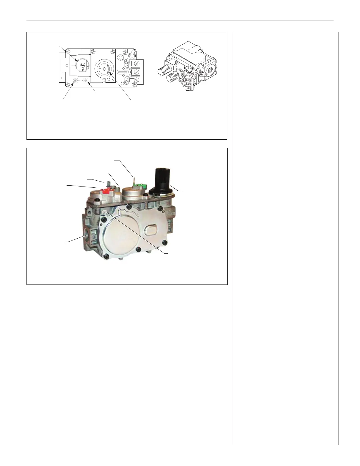
Figure 3: SIT Electronic Gas Valve
Figure 2: SIT Millivolt Gas Valve
Note: The piezo igniter is located behind the lower access panel (see Figure 1).
Variable Flame Height Adjustment
All Millivolt and electronic appliances are
equipped with a variable gas control valve.
Flame height for these models may be
adjusted through a range between fi xed
low and high settings, alternately, while the
appliance is in operation.
Adjust the fl ame height as desired after
lighting the appliance by rotating the variable
adjustment control knob located on the front
of the valve (refer to Figure 2).
H
I
L
O
W
TPTH TP TH
P
I
L
O
T
P
I
L
O
T
O
N
it
O
F
F
HI/LO Flame Control Knob
Manifold Pressure Port
Inlet Pressure Port
Main Gas
Control Knob
IN
OUT
Millivolt Appliances
To light millivolt appliances, refer to the
detailed lighting instructions found on
Page 26 (English) and Page 27 (French).
Millivolt appliance lighting instructions
may also be found on the pull-out lighting
instruction labels attached to the gas
control valve.
Millivolt units are not provided with any
factory-installed controls; therefore, one
of the optional control switches is required
to operate the unit (ON/OFF Wall Switch,
Unit-Mountable ON/OFF Switch, Thermostat,
Remote Control). See “Accessories” in this
manual for details.
Once the pilot is lit, use the switch or remote
control to turn the appliance on or off.
Electronic Appliances
To light electronic appliances, refer to the
detailed lighting instructions on Page 28
(English) and Page 29 (French). Electronic
appliance lighting instructions may also be
found on the pull-out lighting instruction
label attached to the gas control valve.
If your electronic appliance is equipped with
an optional wall switch or remote control kit,
the appliance main burner may be turned
ON and OFF using the wall switch or remote
control.
CPI switch located to the left of the gas valve
switches the pilot from intermittent operation
(pilot goes out when the fi replace is turned
off) to continuous pilot mode. The rocker
switch will not turn the burner on or off.
Orange Wire
(from DFC Wire
Harness)
Main Gas Inlet
3/8 in. NPT
Green Wire
(from DFC Wire Harness)
Line (IN) Test Port
Manifold (OUT) Test Port
Hi/Lo Flame
Control Knob
Yellow Ground Wire
(from DFC Wire Harness)
 Loading...