8
NOTE: DIAGRAMS & ILLUSTRATIONS ARE NOT TO SCALE.
LENNOX HEARTH PRODUCTS • MERIT PLUS
®
DIRECT VENT GAS FIREPLACES (MPD33/35/40/45) • CARE AND OPERATION INSTRUCTIONS
OPERATION AND CARE OF YOUR APPLIANCE
WARNING
Young children should be carefully supervised when they are in the
same room as the appliance. Toddlers, young children and others
may be susceptible to accidental contact burns. A physical barrier is
recommended if there are at risk individuals in the house. To restrict
access to a fi replace or stove, install an adjustable safety gate to keep
toddlers, young children and other at risk individuals out of the room
and away from hot surfaces.
AVERTISSEMENT
Les jeunes enfants devraient être surveillés étroitement lorsqu’ils se trou-
vent dans la même pièce que l’appareil. Les tout petits, les jeunes enfants
ou les adultes peuvent subir des brûlures s’ils viennent en contact avec
la surface chaude. Il est recommandé d’installer une barrière physique
si des personnes à risques habitent la maison. Pour empêcher l’accès à
un foyer ou à un poêle, installez une barrière de sécurité; cette mesure
empêchera les tout petits, les jeunes enfants et toute autre personne à
risque d’avoir accès à la pièce et aux surfaces chaudes.
Gas Controls/Control
Compartment Access
Operation of millivolt and electronic gas
control systems is different. Before lighting
and operating your appliance, determine
whether you have a millivolt or electronic
appliance.
The gas controls can be found behind the
lower access panel.
To open the panel, press the upper right
corner of the panel until the spring-loaded
magnetic catch is released. Then gently pull
the panel forward to release the left magnetic
catch and allow the panel to swing down
to open.
On millivolt systems, the piezo igniter, Hi/
Lo fl ame adjustment knob, pilot and main
gas ON/OFF control knob, and gas valve
(Figure 1) are located behind the lower
access panel.
On electronic systems, the hi/lo fl ame
adjustment knob and gas valve are located
behind the lower access panel.To remove the
lower access panel, slide the hinge pin on
the left side of the panel to the RIGHT until
it disengages from the left corner post hole.
Pull the panel diagonally to the LEFT, away
from the fi replace.
To ease panel replacement, press the spring-
loaded catches to temporarily lock them in
their retracted position, and then close the
panel.
Refer to Figure 1 for access to the gas
control valve. Millivolt appliances will be
fi tted with the gas control valve shown in
Figure 2.
Appliances with electronic systems will be
fi tted with the electronic valve shown in
Figure 3. Familiarize yourself with the gas
control valve that your appliance uses.
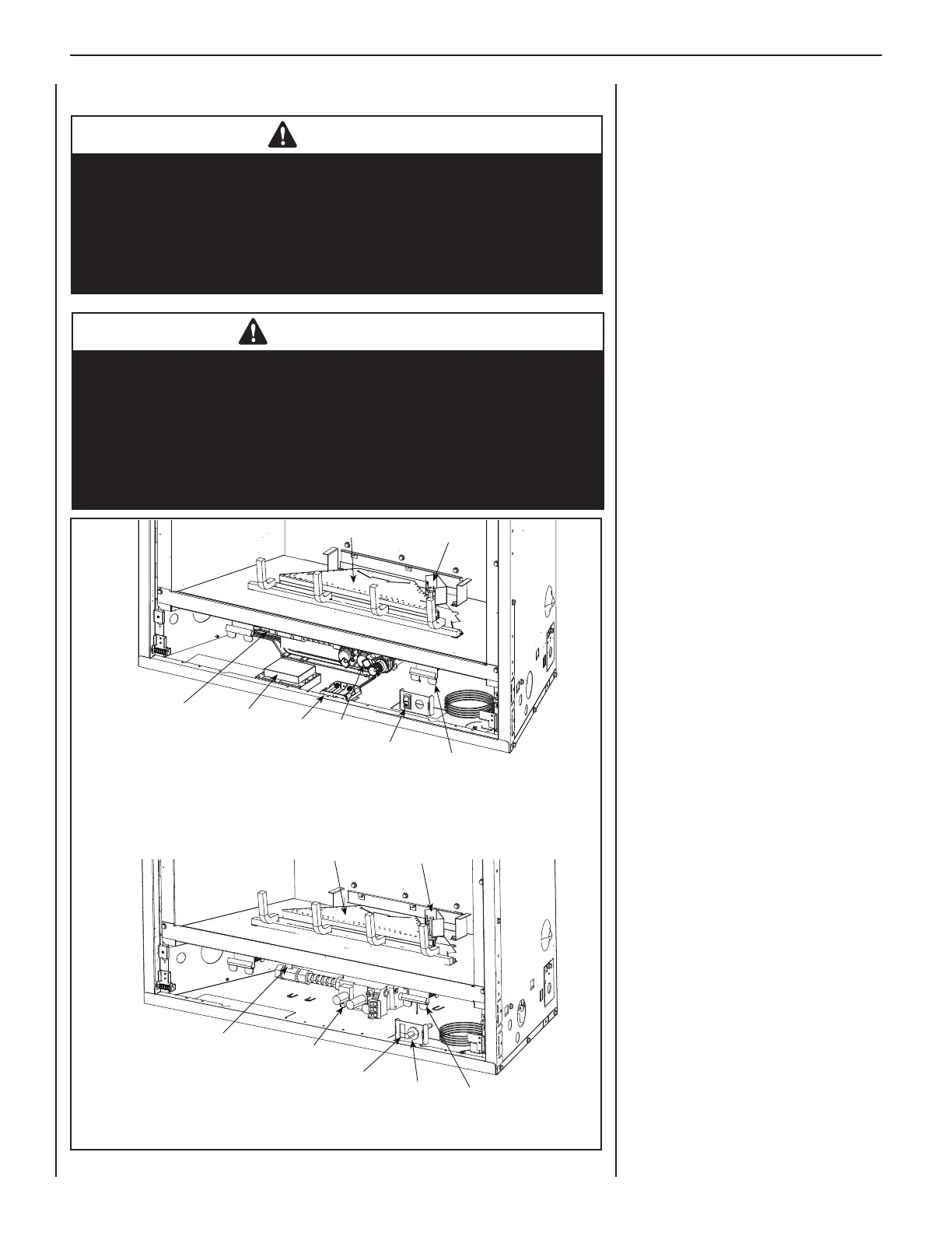
Figure 1: Control Compartment
Pilot Assembly
Burner Assembly
CPI Switch*
Door Latch
Main Gas
Shut-Off Valve
*CPI Switch - Switches from an
intermittent pilot mode to a stand-
ing pilot mode (a standing pilot
stays lit when the fireplace is off).
Gas Valve
Battery
Holder
DFC Board
*CPI Switch Positions
(o) = Intermittent Pilot Mode
(-) = Standing Pilot Mode
Electronic Model
Millivolt Model
Pilot Assembly
Burner Assembly
Piezo
Door Latch
(Optional) Burner
ON/OFF Switch
Main Gas
Shut-Off Valve
Gas Valve
 Loading...