26
NOTE: DIAGRAMS & ILLUSTRATIONS ARE NOT TO SCALE.
LENNOX HEARTH PRODUCTS • MERIT PLUS
®
DIRECT VENT GAS FIREPLACES (MPDP35/40) • INSTALLATION INSTRUCTIONS
Step 5. FIELD WIRING
CAUTION
The ground supply lead must be
connected to the wire attached
to the green ground screw
located on the outlet box (see
wiring diagrams). Failure to
do so will result in a potential
safety hazard. The appliance
must be electrically grounded
in accordance with local codes
or, in the absence of local codes,
the National Electrical Code,
ANSI/NFPA 70-latest edition (in
Canada, the current CSA C22.1
Canadian Electrical Code).
CAUTION: Label all wires prior to discon-
nection when servicing controls. Wiring
errors can cause improper and dangerous
operation.
ATTENTION: Au moment de l’entretien
des commandes, étiquetez tous les fils
avant de les débrancher. Des erreurs
de cáblage peuvent entraîner un fonc-
tionnement inadéquat et dangereux.
Verify proper operation after servicing.
S’assurer que l’appareil fonctionne adé-
quatement une fois l'entretien terminé.
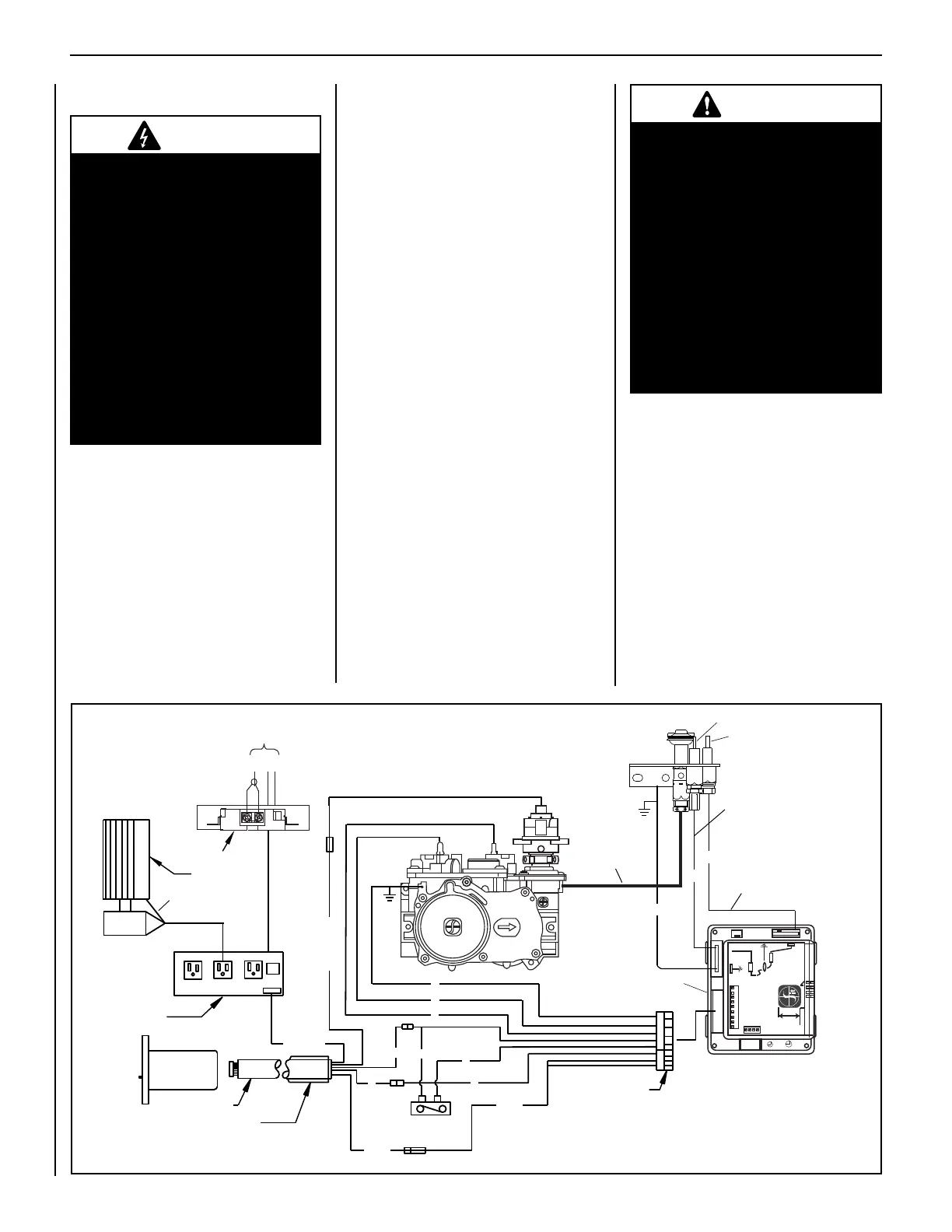
Electronic Wiring (see Figures 50 and 51)
All models must be connected to the main
power supply.
1. Route a 3-wire 120Vac 60Hz 1ph power
supply to the appliance junction box.
2. Remove the electrical inlet cover plate
from the side of the unit by removing the
plate's securing screws. See Figure 12 on
Page 10.
3. Remove the cover plate's knockout and
then feed the power supply wire through
the knockout opening and into the unit
junction box.
4. Connect the black power supply wire to the
lower outlet's red and black pigtail leads
and the white power supply wire to the
common terminal of the outlet as shown
in Figures 50 and 51.
5. Connect the ground supply wire to the
pigtail lead attached to outlet's green
ground screw.
6. After the wiring is complete, replace the
cover plate.
7. Acquire and locate a standard junction
box on the wall adjacent to the appliance
within the reach of the remote system
umbilical cord wiring harness. Position
the 14 pin terminal within the junction box
in preparation for its attachment to the
remote receiver.
Figure 50
8. When wall finish is complete install the
receiver in the previously located junction
box and connect the 14 pin terminal to
the 14 pin connector on the back of the
receiver.
9. Install the receiver cover plate, taking care
to ensure the receiver switch is properly
indexed with the switch cover when align-
ing the components for attachments.
WARNING
Electronic models of these appli-
ances are equipped with a three-
prong (grounding) plug utilized
in connecting the electronic
components to the junction box
in the lower compartment. This
grounding plug provides protec-
tion against shock hazard and
should be plugged directly into
the properly grounded three-
prong receptacle. DO NOT cut
or remove the grounding prong
from the plug.
DFC WIRE HARNESS
PROFLAME DFC BOARD
UNIT MOUNTED
ROCKER SWITCH*
PILOT TUBE
FAN
POWER CORD
POWER CORD
CABLE HARNESS
HIGH-TEMP SLEEVE
FAN CONTROL
MODULE
WALL
RECEIVER
DIGITAL
FIREPLACE
BURNER
CONTROL
SPARK WIRE
CABLE
PILOT SENSOR
CABLE
IGNITER ROD
FLAME
SENSOR
PROFLAME
ELECTRONIC
VALVE
JUNCTION BOX
* Unit Mounted Rocker Switch
OFF (o) = Intermittent Pilot Mode
ON (-) = Standing Pilot Mode
Y
120V
Out
Fan
Power
Aux
Out
B
W
G
CAV 021
Schematic Representation Only
PILOT BURNER
IGNITER-SENSOR
ASSEMBLY
B
B
Wiring Color Code
B = Black
BL = Blue
BR = Brown
G = Green
GY = Gray
O= Orange
PU = Purple
W = White
R = Red
P = Pink
Y = Yellow
O
W
W
W
Y
G G
G
G
B, BR, Y, O
P, BL
P, BL
R,PU,GY
NOTES:
1. If any of the original wire as supplied must be re-
placed, use Type AWM 105°C - 18 gage wire ONLY.
2. 120 VAC, 60 Hz - Less than 5 Amps.
CAUTION: label all wires prior to disconnection
when servicing controls. Wiring errors can cause
improper and dangerous operation. Verify proper
operation after servicing.
ELECTRONIC
IGNITION WIRING
DIAGRAM
*Unit Mounted CPI Rocker Switch
 Loading...