27
NOTE: DIAGRAMS & ILLUSTRATIONS ARE NOT TO SCALE.
LENNOX HEARTH PRODUCTS • MERIT PLUS
®
DIRECT VENT GAS FIREPLACES (MPDP35/40) • INSTALLATION INSTRUCTIONS
Step 6. REMOTE CONTROL SYSTEM
The remote control system allows you to operate
your fireplace from the comfort of your chair
and is configured to control the ON/OFF primary
burner operation, its flame levels (through six
levels) and provides ON/OFF and Smart ther-
mostatic control of the appliance
The system controls fan speed through six (6)
levels and has a constantly powered 120V/60Hz
power outlet.
The Receiver connects directly to the gas valve,
stepper motor and the Fan Control Module with
and umbilical cord wiring harness.
The Receiver is powered by 4 AA type batteries,
located within.
The Receiver accepts commands via radio
frequency from the Transmitter and does not
require line-of-sight operation.
The Receiver three position slider switch can
be set to one of three positions: ON (Manual
Override), REMOTE (Remote Control) or OFF.
CAUTION
Property damage hazard. Excessive
heat can cause property damage. The
appliance can stay lit for many hours.
Turn off the appliance if it is not going
to be attended for any length of time.
Always place the Transmitter where
children cannot reach it.
WARNING
Fire hazard. Can cause severe
injury or death. The receiver causes
ignition of the appliance. The appli-
ance can turn on suddenly. Keep
away from the appliance burner
when operating the remote system
or activating manual bypass of the
remote system.
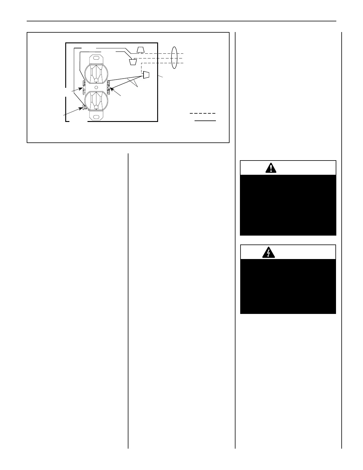
Figure 51- J-Box Wiring
Green
Ground
Screw
Black
Hot
Side of
Receptacle
Tab Intact
Tab Intact
Green
White
Neutral
Side of
Receptacle
120 VAC - Black
Neutral - White
Ground - Green
J-BOX / RECEPTACLE
WIRING
120V, 60HZ, 1PH
Junction Box
Field Wired
Factory Wired
Low Battery Power Detection
The life span of the Receiver batteries depends
on various factors: quality of the batteries used,
the number of ignitions of the appliance, the
number of changes to the room thermostat
set point, etc.
When the Receiver batteries are low, two
"beeps" will be emitted from the Receiver when
it receives and ON/OFF command from the
Transmitter. This is an alert for a low battery
condition for the Receiver. When the batteries
are replaced the "beep" will be emitted from the
Receiver when the ON/OFF key is pressed (See
Initializing The System).
Refer to the fireplace Care and Operation
Instructions for detailed remote control system
operation instructions.
Initializing The System For The First Time
Install the 4 AA batteries into the receiver battery
bay (behind the wall switch plate).
Note: The polarity of the battery and insert
into the battery bay as indicated on the Battery
cover (+/-).
Place the 3 position slider switch on the wall
receiver in the "Remote" position (see Figure 50
and Page 35). Using the end of a paper clip, or
other similar object, insert the end of the paper
clip into the hole marked "PRG" on the Receiver
front cover. The Receiver will "beep" three (3)
times to indicate that it is ready to synchronize
with a Transmitter.
Install the 3 AAA type batteries in the Trans-
mitter battery bay, located on the base of the
Transmitter. With the batteries already installed
in the Transmitter, push the ON button. The
Receiver will "beep" four times to indicate the
Transmitter's command is accepted and sets
to the particular code of that Transmitter. The
system is now initialized.
 Loading...