16
Prevailing Winds
Normally wind bafes are not required for a outdoor unit.
However, in order to maximize reliability and performance,
the following best practices should be followed.
If unit coil cannot be installed away from prevailing winter
winds, some method of protecting the coil is recommended.
However, minimum clearances as reference in “Figure 11.
Outdoor Unit Clearances - Inches (mm)” on page 11
must be observed at all times.
Common application examples are:
• When prevailing winds are from the air inlet side, then
position the wind barrier a minimum of 12 inches (305
mm) from the unit as illustrated in “Figure 23. Wind
Barrier”
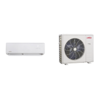
• When prevailing wind is into the discharge side, then
position the wind barrier a minimum 79 inches (2007
mm) from the front of the unit as illustrated in Figure
14. Wind Barrier”
• Outdoor unit can be installed in a dog house style shel-
ter as illustrated in “Figure 24. Dog House-Style Shel-
ter”
• Outdoor unit can be installed in a alcove or under a
roof overhang as illustrated in “Figure 25. Unit Installed
in Alcove”
12” (305mm)
Min. Distance
Wind Barrier
Inlet Air
Prevailing Winter Winds from Air Inlet Side
Discharge Air
Wind Barrier
Prevailing Winter Winds From Air Discharge Side
79” (2007mm)
Min. Distance
Figure 23. Wind Barrier
12 in
305 mm
24 in
610 mm
24 in
610 mm
12 in
305 mm
NOTE - Minimum clearances shown.
Figure 24. Dog House-Style Shelter
12 in
305 mm
24 in
610 mm
12 in
305 mm
24 in
610 mm
NOTE - Minimum clearances shown.
Figure 25. Unit Installed in Alcove
Buried Refrigerant Pipe Protection
• All refrigerant lines must be insulated regardless of if
it is buried
• In addition to insulating each line of piping, buried lines
must rest inside a sealed, watertight conduit
• The conduit must be designed so it cannot collect and
retain water
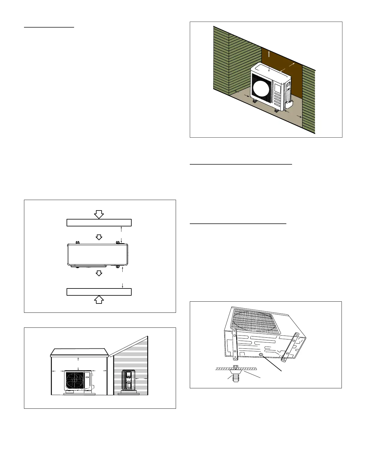
Outdoor Unit Condensate Piping
Condensate formed during the heating and defrost
processes must be drained from heat pump units. Drain
holes are provided in the base of the units to ensure proper
drainage. Heat pumps must be raised when installed on a
concrete pad or the ground to allow drainage to occur. If
the heat pump unit is installed on wall mounting bracket,
insert the provided drain connector into one of the 1
inch (25 mm) drain holes and attached a eld-provided
insulated drain hose to the connector. Use eld-provided
rubber plugs to cover any unused drain holes as illustrated
in “Figure 26. Condensate Drain”.
Drain
Connector
Chassis
Condensate Drain
(location varies per model)
Figure 26. Condensate Drain
 Loading...