17
Securing the Outdoor Unit
Slab or Roof Mounting
Install the unit a minimum of 4 inches (102 mm) above the
roof or ground surface to avoid ice build-up around the
unit. Place the unit above a load bearing wall or area of
the roof that can adequately support the unit. Consult local
codes for rooftop applications.
CAUTION
Roof Damage!
This system contains both refrigerant and oil. Some
rubber roong material may absorb oil. This will cause
the rubber to swell when it comes into contact with oil.
The rubber will then bubble and could cause leaks.
Protect the roof surface to avoid exposure to refrigerant
and oil during service and installation. Failure to follow
this notice could result in damage to roof surface.
Securing Outdoor Unit to Slab, Frame, or Rails
If the outdoor unit is installed on a eld-provided slab or
frame, use lag bolts or equivalent to secure the outdoor
unit to the slab or frame.
Four Field-provided Anchor Bolts
Figure 27. Securing Outdoor Unit to Slab
Four Field-Provided
Anchor Bolts
Figure 28. Securing Outdoor Unit to Rails
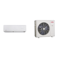
Securing Outdoor Unit to Hanging Brackets
If the outdoor unit is installed on eld-provided wall
mounting brackets, use lag bolts or equivalent to secure
the outdoor unit to the bracket. Minimum rear clearance
can be reduced to 6 inches (152 mm) when mounted on
brackets and with no obstructions on the other three sides.
Allow for condensate disposal when placing units above
one another.
Air Outlet
Air Inlet
6 in
152 mm
Figure 29. Securing Outdoor Unit to Brackets
Refrigerant Piping Connections
Line sets consists of two copper pipes connecting the
outdoor unit to the indoor unit. “Table 5. Refrigerant Piping
and Indoor Unit Connection Sizes” on page 18 lists
the connection sizes. The connections are made using
the provided brass are nuts at the end of the refrigerant
piping connections.
1. Choose the correct pipe sizes for your application
using “Table 5. Refrigerant Piping and Indoor Unit
Connection Sizes” on page 18.
2. Conrm that you are using the correct diameter piping.
3. Determine the necessary piping length required for the
application.
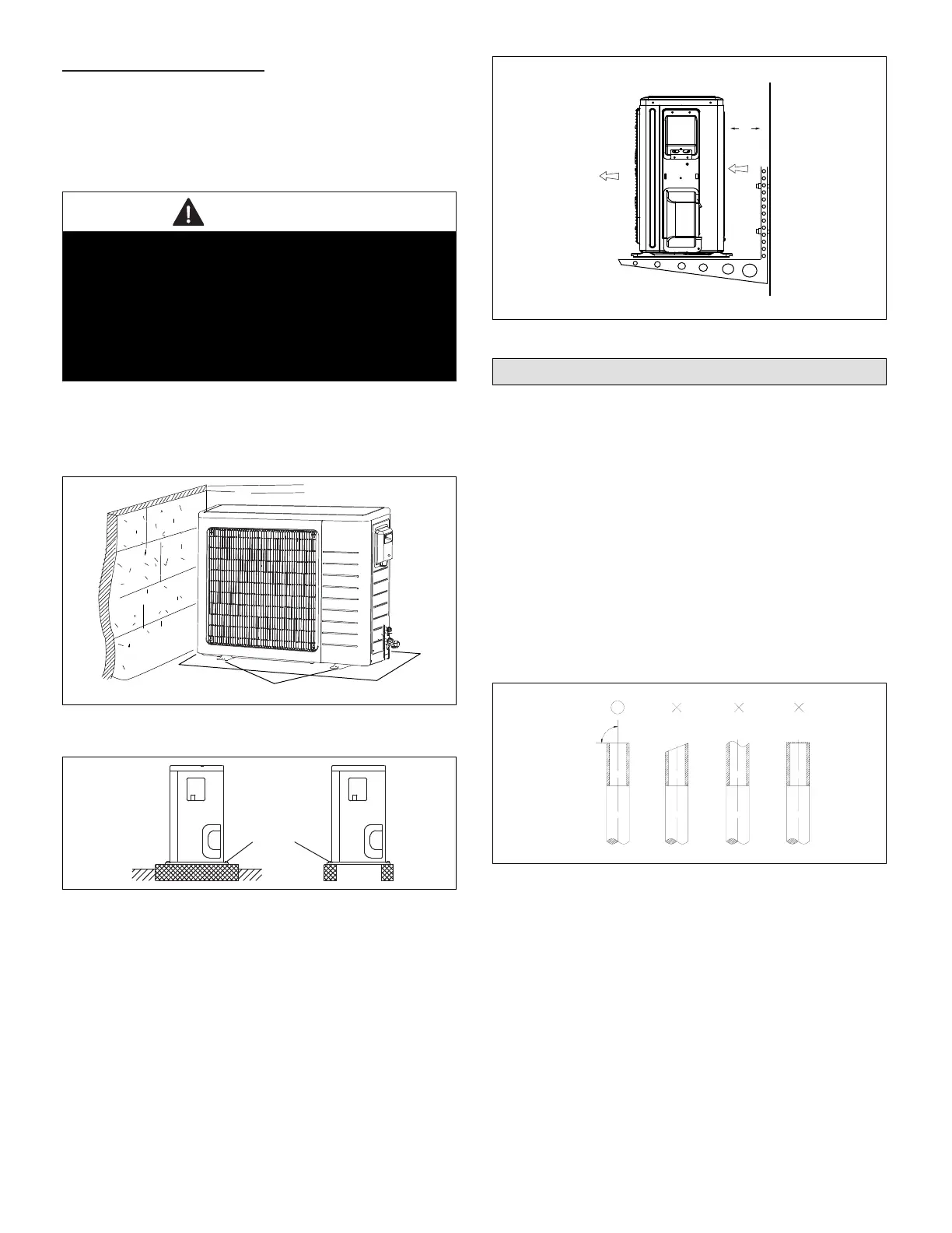
4. Cut the selected pipes with a pipe cutter. Make the cuts
at and smooth as illustrated in “Figure 30. Cutting
Piping”.
Figure 30. Cutting Piping
5. Insulate the copper piping.
6. Insert a are nut onto each pipe before aring.
7. Use “Table 4. Flaring Piping” on page 18 to properly
are the pipe.
 Loading...