9
Wiring
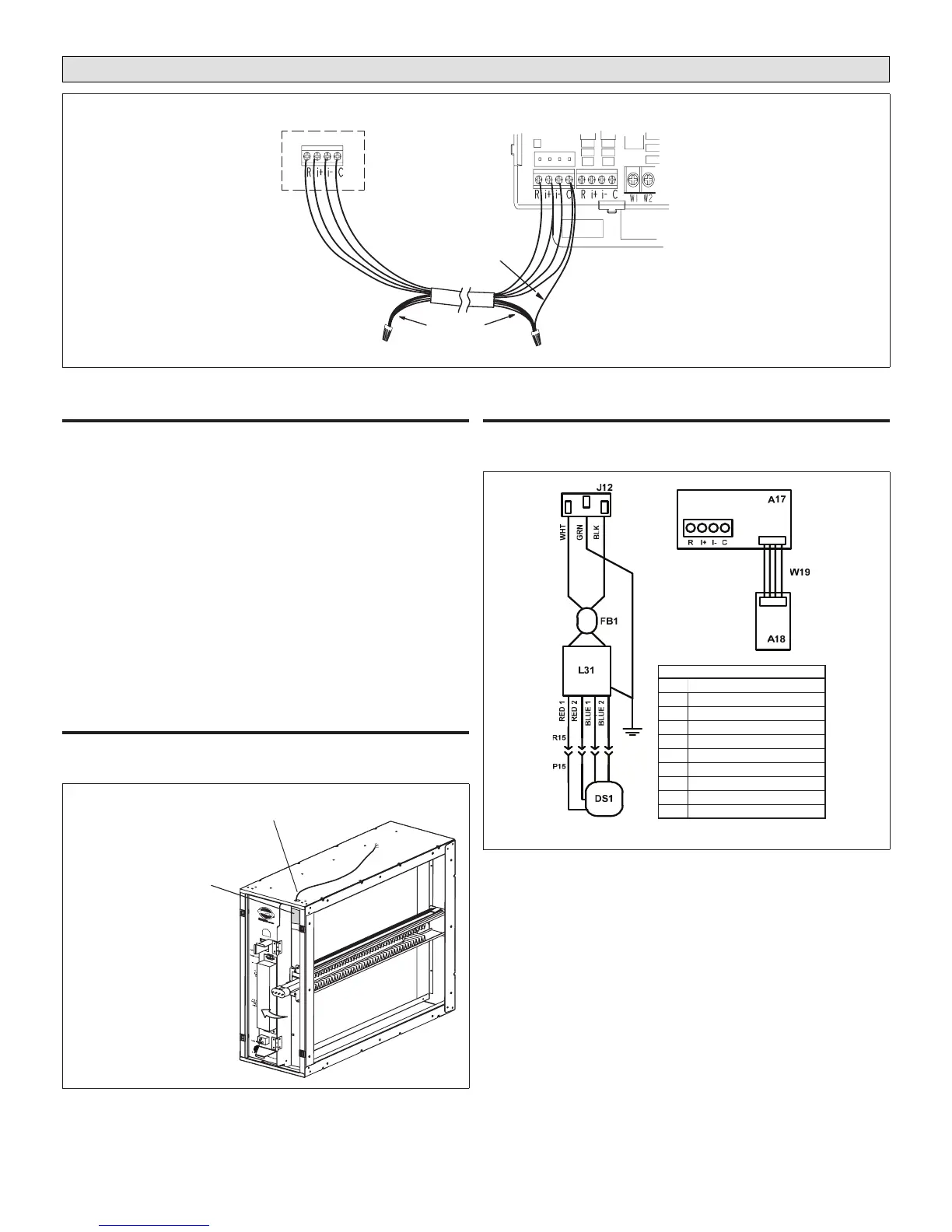
Unused wires
Single wire
to terminal “C”.
Indoor Unit Controller
PureAir S
Figure 10. Communicating and Low Voltage Connections
commUnication Wiring
Communicating systems requires four thermostat wires
between the PureAir S and the Lennox Communicating
Indoor Control. When a thermostat cable with more
than four wires is used, the extra wires must be properly
connected to avoid electrical noise. The wires must not be
left disconnected. See “Figure 10. Communicating and Low
Voltage Connections”.
• Use wire nuts to bundle the unused wires at each end of
the cable. A single wire should then be connected to the
indoor unit end of the wire bundle and attached to the “C”
terminals.
• Keep all communication wiring as far away from the
house electrical wiring and large electrical appliances as
possible. Recommended minimal distance is 15 feet (5
meters).
commUnication Wiring roUting
Communication wiring to the indoor unit is routed through
the opening in the top of the cabinet as illustrated below.
Route communication wiring through
grommet to indoor unit
iComfort Communicating
PCO Control
Figure 11. Routing of Communication Wiring
pUreair S internal factory Wiring
The should be wired in accordance with national and local
codes.
KEYCOMPONENT
DS1UVA LAMP / LAMPHOLDER
P15PLUG
R15REC EPTACLE
L31BALLAST
J12JACK
FB1FERRITE BEAD
A17MAIN SENSOR BOARD
A18UVA SENSOR BOARD
W19INT ERCONNEC T WIRE
LEGEND
Figure 12. PCO Wiring Schematic
 Loading...