23
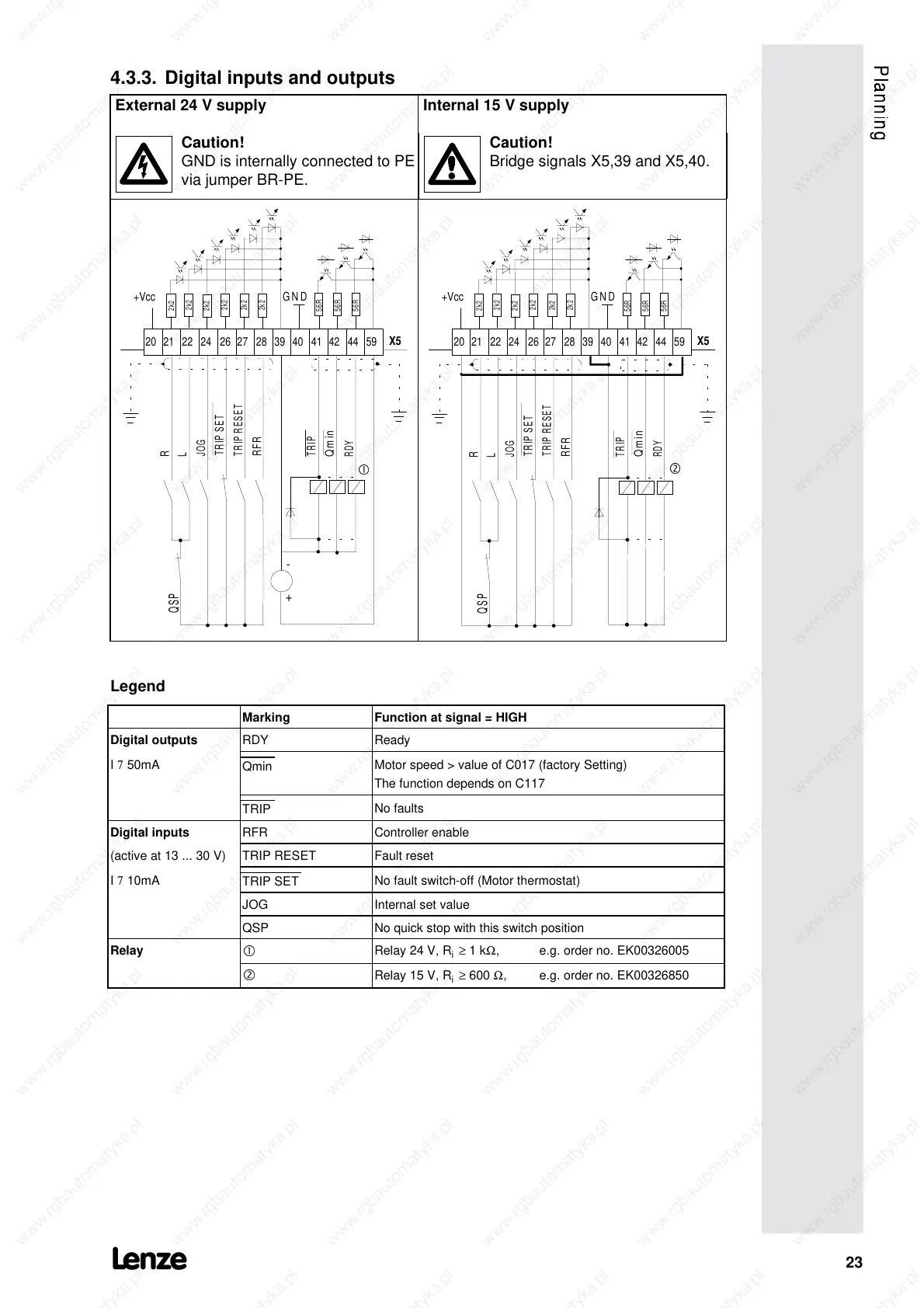
4.3.3. Digital inputs and outputs
External 24 V supply Internal 15 V supply
Caution!
GND is internally connected to PE
via jumper BR-PE.
Caution!
Bridge signals X5,39 and X5,40.
-
QSP
R
L
JOG
TRIP SET
TRIP RESET
RFR
TRIP
RDY
X5
Qmin
20 21 22 24 26 27 28 39 40 41 42 44 59
+
+Vcc
GND
2k2
2k2
2k2
2k2
2k2
2k2
56R
56R
56R
c
QSP
R
L
JOG
TRIP SET
TRIP RESET
RFR
TRIP
RDY
Qmin
X5
20 21 22 24 26 27 28 39 40 41 42 44 59
+Vcc
GND
2k2
2k2
2k2
2k2
2k2
2k2
56R
56R
56R
d
Legend
Marking Function at signal = HIGH
Digital outputs
RDY Ready
I
7
50mA
Qmin
Motor speed > value of C017 (factory Setting)
The function depends on C117
TRIP
No faults
Digital inputs
RFR Controller enable
(active at 13 ... 30 V) TRIP RESET Fault reset
I
7
10mA
TRIP SET
No fault switch-off (Motor thermostat)
JOG Internal set value
QSP No quick stop with this switch position
Relay
c
Relay 24 V, R
i
≥
1 k
Ω
, e.g. order no. EK00326005
d
Relay 15 V, R
i
≥
600
Ω
, e.g. order no. EK00326850
 Loading...