Electrical installation
Communication
Connection of PROFIBUS
4
57
MA 13.0001 DE-EN DE/EN 2.0
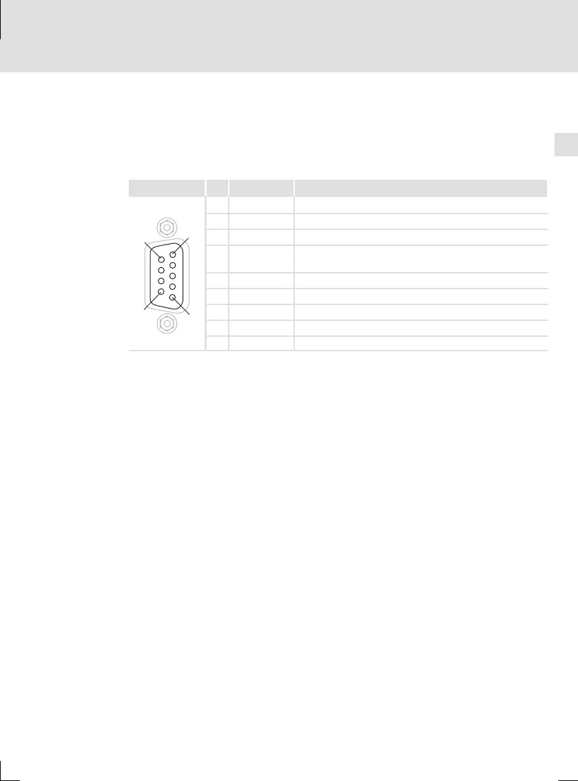
4.7.3 Connection of PROFIBUS
Assignment of Sub-D socket
The controller is connected to the PROFIBUS via the 9-pin Sub-D socket
X4.1/X4.2.
View Pin Designation Explanation
1
6
5
9
1 - -
2 - -
3 RxD/TxD-P Data line B (received/transmitted data plus)
4 RTS Request to send
(received/transmitted data, no differential signal)
5 M5V2 Data reference potential (ground to 5V)
6 P5V2 5VDC/30mA(bustermination)
7 - -
8 RxD/TxD-N Data line A (received/transmitted data minus)
9 - -
 Loading...