 Loading...
Do you have a question about the Lenze 9400 Series and is the answer not in the manual?
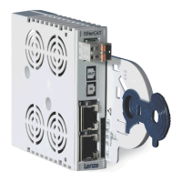
| Control | Vector control, Servo control |
|---|---|
| Protection class | IP20 |
| Communication interfaces | EtherCAT, PROFIBUS, CANopen, PROFINET, EtherNet/IP |
| Feedback systems | Resolver, EnDat, Hiperface |
| Cooling | liquid cooling |
| Safety | STO, SS1, SLS, SBC, SDI |
Details revisions and updates made to the manual over time.
Explains typographical and formatting conventions used throughout the document.
Provides definitions for technical terms and acronyms used in the manual.
Clarifies the meaning of signal words and symbols indicating danger or important information.
Provides essential safety measures for handling and operating Lenze drive and automation components.
Details safety precautions specific to the communication module and its application.
Highlights potential dangers and necessary measures related to electrical and electrostatic hazards.
Defines the intended use and scope of the EtherCAT communication module.
Explains how to identify the communication module's type and version from its nameplate.
Lists the key technical features and capabilities of the EtherCAT communication module.
Details the physical terminals and communication interfaces available on the module.
Provides general specifications and environmental operating conditions for the module.
Details the electrical insulation specifications and safety requirements.
Specifies data formats and characteristics for communication protocols.
Outlines the timing aspects of parameter and process data transfer.
Provides the physical dimensions of the communication module.
Guides on how to physically mount and dismount the communication module.
Details wiring procedures, network topology, and connection specifications.
Important checks and notes to perform before powering on the system for the first time.
Steps for configuring the EtherCAT master for communication with the module.
Configuration options and displays available within the Lenze »Engineer« software.
Defines how to assign station addresses and aliases in the EtherCAT network.
Explains the setup and use of Distributed Clocks for precise time synchronization.
Instructions for establishing an online connection to field devices using the »Engineer« software.
Guides on finding EtherCAT ADS parameters in Beckhoff TwinCAT and Lenze Engineer.
Procedures for initial system startup, parameter saving, and restart behavior.
Describes the structure and components of an EtherCAT telegram.
Details the structure and contents of EtherCAT datagrams used for data exchange.
Illustrates the state transitions of an EtherCAT slave during communication startup.
Explains how to configure Process Data Objects (PDO) for data exchange.
Step-by-step guide to mapping process data using the Lenze »Engineer« software.
Details the mapping indices and codes used for PDO configuration.
Describes the process of establishing SDO communication between master and slave.
Covers the procedures for reading and writing parameters via SDO.
Lists and describes the communication objects and their attributes.
Details SDO abort codes used to indicate errors during parameter transfer.
Describes how the module detects and responds to EtherCAT communication interruptions.
Details responses to communication errors between the module and the standard device.
Explains the monitoring of EtherCAT PDO telegrams for failures.
Describes how the system detects and reacts to loss of EtherCAT synchronization.
Explains the status indications provided by the module's LEDs.
Lists EtherCAT error numbers, names, default responses, and adjustability.
Provides detailed causes and remedies for various EtherCAT error messages.
Lists communication-relevant parameters of the Servo Drive 9400.
Details parameters specific to the EtherCAT communication module in slot MXI1.
Details parameters specific to the EtherCAT communication module in slot MXI2.
Provides a table summarizing parameter attributes like data type, access, and index.


