Commissioning
5-5
BA9300SU EN 2.1
5.2.1 Operation with synchronous motors made by other manufacturers
Note!
If you use a Lenze synchronous motor with encoder feedback, you may skip this chapter.
Stop!
Please use single pole resolvers and single-turn or multi-turn sin/cos encoders only.
5.2.1.1 Rotor position adjustment
The rotor position must be adjusted, if:
• a motor other than from Lenze is used
• another encoder is mounted to the motor later (motor from another manufacturer but also
Lenze motors)
• a defective encoder has been replaced
The following steps are required:
1. Check the resolver poling
2. Optimise the current controller
Resolver poling
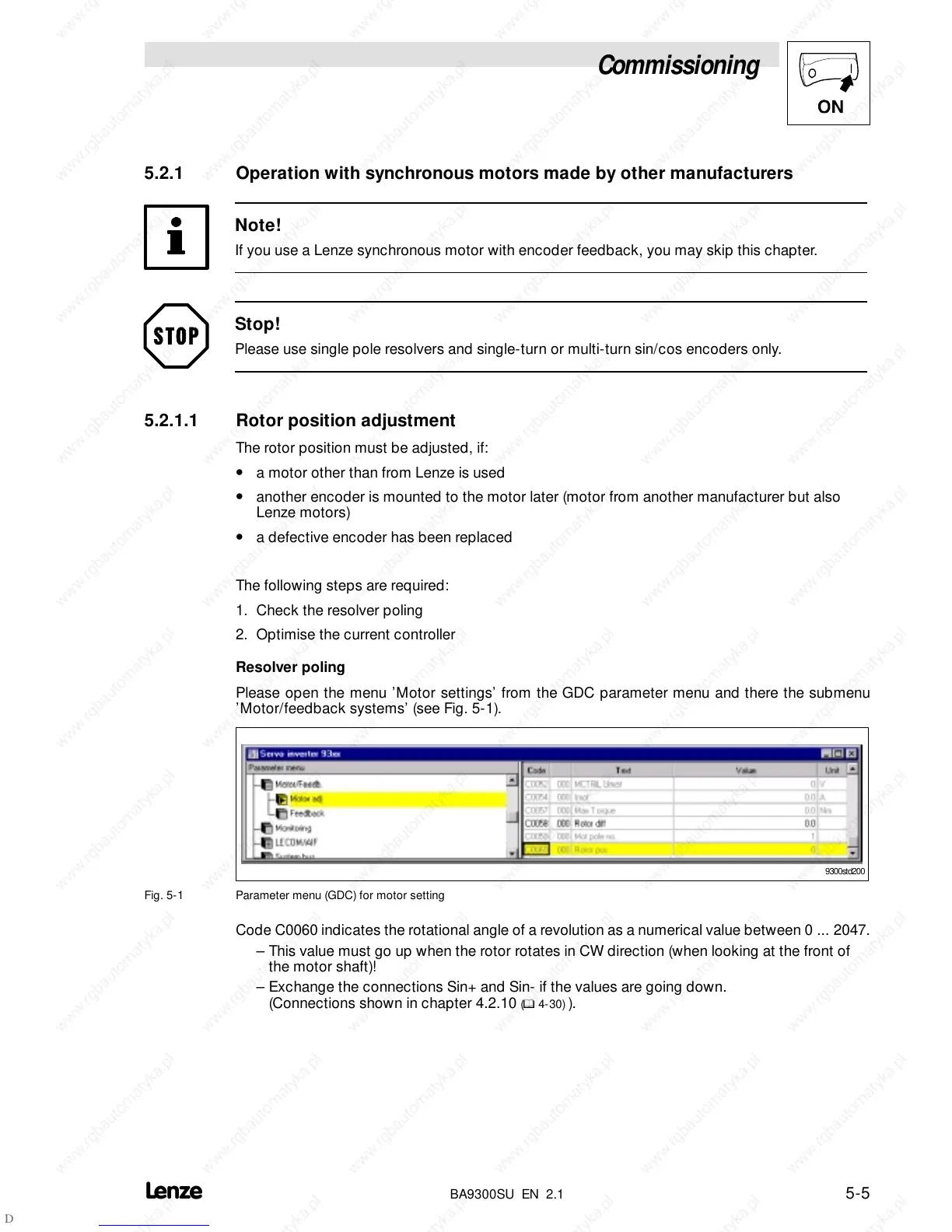
Please open the menu ’Motor settings’ from the GDC parameter menu and there the submenu
’Motor/feedback systems’ (see Fig. 5-1).
9300std200
Fig. 5-1 Parameter menu (GDC) for motor setting
Code C0060 indicates the rotational angle of a revolution as a numerical value between 0 ... 2047.
– This value must go up when the rotor rotates in CW direction (when looking at the front of
the motor shaft)!
– Exchange the connections Sin+ and Sin- if the values are going down.
(Connections shown in chapter 4.2.10
(
^
4-30) ).
 Loading...