Mechanical installation
Transport
4
20
Lenze ¯ MA 12.0012 ¯ 4.0
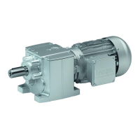
g500−H45 ... g500−H140
G50AH045...G50BH114
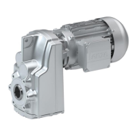
g500−H210 ... g500−H3000
G50BH121...G50BH230
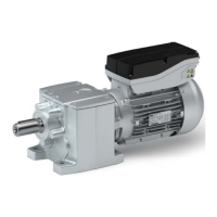
g500−H5000 ... g500−H14000
G50BH250...G50BH314
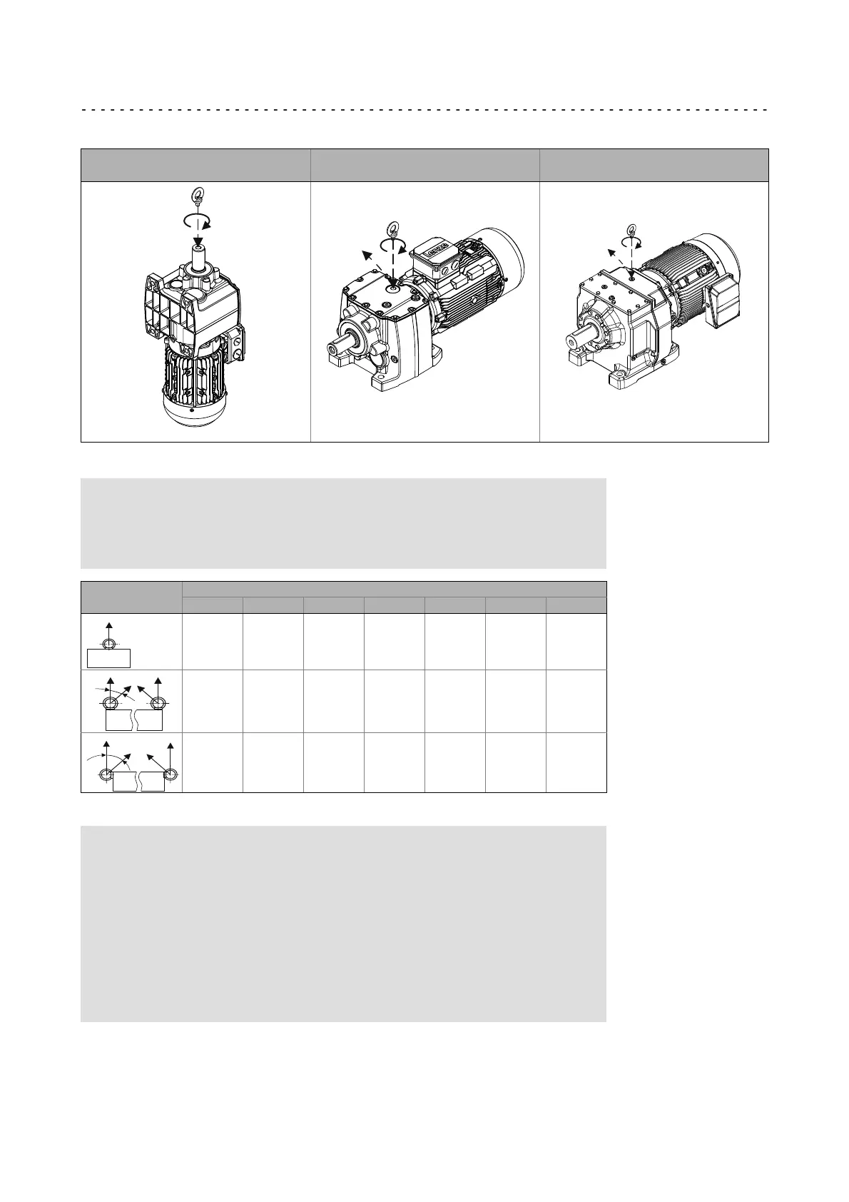
1.
2.
1.
2.
Fig. 2 Position of the eye bolt for transporting the complete drive system
Note!
As standard, threads are delivered with plug screws. The plug can be
easily removed, e.g. by using a screwdriver blade. For the thread size and
load carrying capacity of the eye bolt, please see Tab. 1.
Eye bolt position
Thread
M6 M8 M10 M12 M16 M20 M24
80 140 230 340 700 1200 1800
£45°
−−−−− 100 170 240 500 860 1290
£45°
−−−−− 70 115 170 350 600 900
Tab. 1 Load carrying capacity of each eye bolt in kg
Danger!
Completely screw in transport aids (such as eye bolts or bearing plates),
they must be flat and applied over their entire surface!
If possible, the transport aids (such as eye bolts or bearing plates) must
be stressed vertically in the direction of the screw axis! Angular tension or
tension to the sides reduces the payload! Observe the information
provided in DIN 580!
Use additional appropriate lifting aids, if required, to achieve a direction
of loading which is as vertical as possible (highest payload). Secure lifting
aids against shifting!
 Loading...