Mechanical installation
Preparation
Maximum permissible load at the motor adapter
4
26
Lenze ¯ MA 12.0012 ¯ 4.0
Gearbox with output flange
¯ Especially with regard to applications with an alternating load, Lenze
recommends...:
– the use of anaerobic adhesive between the gearbox flange and mounting area
in order to increase the friction fit;
– with steel or cast iron output flanges, the use of screws with a strength of 10.9
with correspondingly high tightening torques.
4.3.5 Maximum permissible load at the motor adapter
Stop!
¯ The loads generated by the motor mounted must be checked!
¯ The forces F
M
mentioned (see following tables) at the adapter must
not be exceeded!
For the effective force F
M
, static forces (e.g. weight) and dynamic forces (e.g.
acceleration forces, for example caused by vibrations or start−up processes) have to be
taken into consideration.
Furthermore the loading case of the force F
M
has to be taken into consideration:
Loading case k
loading
case
Static 1
Dynamic−pulsating 0.8
Dynamic−alternating 0.6
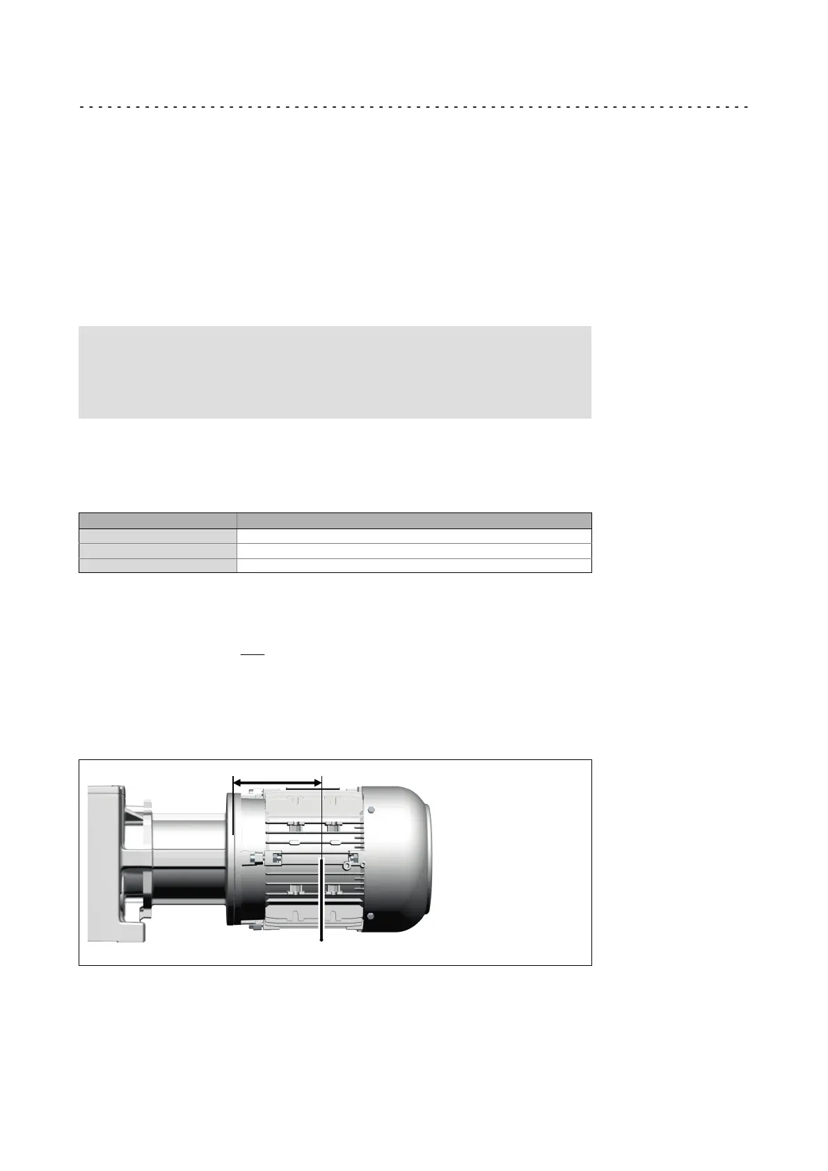
The position of the motor‘s centre of gravity, including all motor options, must be
calculated. If the distance of the centre of gravity L
Tab
is greater, the permissible force
must be reduced as follows.
F
Mzul
+ k
Lastfall
@ F
MTab
@
L
Tab
L
v k
Lastfall
@ F
MTab
If forces act from several directions, e.g. in the case of a moving horizontal travelling
drive, the acting forces have to be added vectorially (e.g. vertical force due to weight plus
horizontal acceleration force).
F
Mperm
corresponds to the maximum value of the forces added vectorially!
L
F
M
If the permissible force F
Mperm
is exceeded, the motor has to be supported in a suitable,
distortion−free fashion!
 Loading...