Mechanical installation
Mounting
Mounting the shrink disc
5
36
Lenze • BA 12.0023 • 9.0
1.
5.
1
1
2
2
KL_GFL06_001-dms
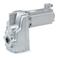
Fig. 7
1Protectioncover
2 Clamping screws
1. Remove protective cap (1), if available.
2. Check machine shaft
– Diameter in fit tolerance h6
– Surface roughness R
z
15 m
3. Thoroughly clean and degrease hollow shaft bore and machine shaft.
Note!
Thoroughly degrease the bore over the entire hollow shaft length to
make sure that remainders of the anticorrosion agent will not be carried
off into the area of the shrink disc when pushing on the machine shaft.
4. Slightly loosen clamping screws (2) one after the other, do not unscrew!
5. Push drive onto machine shaft.
6. Slightly tighten clamping screws manually.
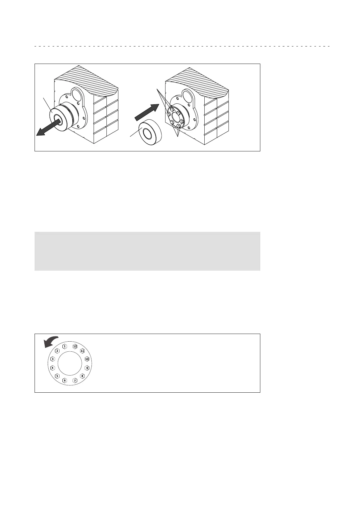
7. Tighten clamping screws (2) one after the other (see Fig. 8) in several passes, with
rising torque, evenly until the indicated screw-tightening torque (see Tab. 7 ) is
reached at all screws.
GT-GNG-003.iso/dms
Fig. 8 Explanation: ”one after the other”
Tip!
Several (in general more than 5 ) passes are necessary until the full
tightening torque is reached at all screws!
 Loading...