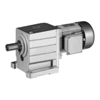
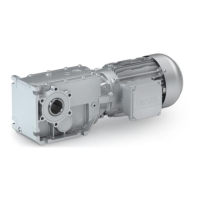
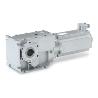
Mechanical installation
Mounting
Mounting the shrink disc
5
37
Lenze • BA 12.0023 • 9.0
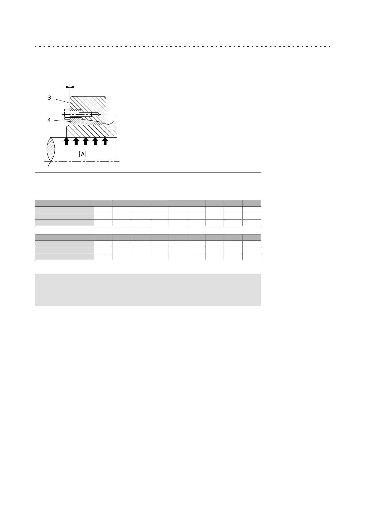
The shrink disc is mounted correctly and fixed when the faces of the outer ring and the
inner ring are aligned (Fig. 9). Minimum misalignments are permissible.
GT-GNG-001.iso
Fig. 9 Hollow shaft with shrink disk
3 Outer ring
free of grease
4 Inner ring
Hollow shaft bore [mm] 20 25 28 30 35 40 45
Clamping screw thread M6 M6 M8 M8 M6 M8 M8 M8 M8
Width across flats 10 10 13 13 10 13 13 13 13
Torque [ Nm ] 12 12 30 30 12 30 30 30 30
Hollow shaft bore [mm] 50 60 65 75 80 85 90 95 100
Clamping screw thread M8 M10 M10 M10 M10 M10 M12 M12 M12
Width across flats 13 16 16 16 16 16 18 18 18
Torque [ Nm ] 30 59 70 70 70 70 125 100 100
Tab. 7 Tightening torque for the clamping screws
Note!
If a different tightening torque is indicated on the shrink disc, this
tightening torque has priority over the value indicated in the table.
8. Push protective cap (1, Fig. 7) onto the shrink disc.
Tip!
For finding out the cause of non-reached torques of the shrink disc
connection, please go through the troubleshooting list in chapter 9.
 Loading...