10
Electrical installaon
Operang Instrucons i510-Cabinet
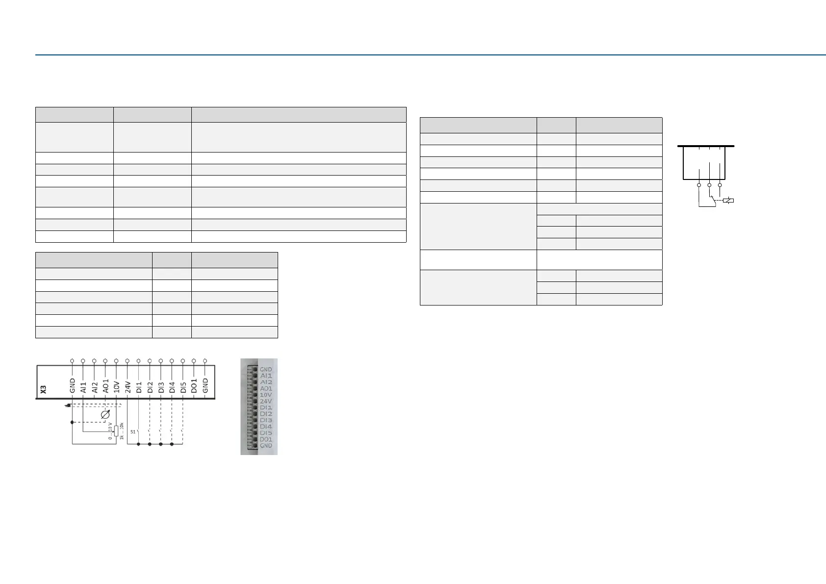
5.3 Control terminals
BasicI/O
Input/output Terminal X3 Informaon
Digital inputs DI1, DI2, DI3, DI4, DI5 DI3/DI4 can be oponally used as frequency or encoder input.
HIGH acve/LOW acve switchable LOW = 0 ... +3 V, HIGH = +12 V
... +30 V
Digital outputs DO1 Digital output (max. 100 mA)
Analog inputs AI1, AI2 Can be oponally used as voltage input or current input.
Analog outputs AO1 Can be oponally used as voltage output or current output.
10-V output 10 V Primarily for the supply of a potenometer (1 ... 10 kΩ). Max.
10 mA
24-V output 24 V Primarily for the supply of digital inputs. (Max. 100 mA)
Reference potenal GND
Connecon system Plug-in spring terminal
Inverter [kW] 0.25 ... 15
Connecon Control terminals X3
Connecon type Plug-in spring terminal
Max. cable cross-secon mm² 1.5
Stripping length mm 9
Tightening torque Nm -
Tools required 0.4 x 2.5
Control terminals
5.4 Relay output
The relay is not suitable for direct switching of an electromechanical holding brake. Use a
corresponding suppressor circuit in case of an inducve or capacive load.
Inverter [kW] 0.25 ... 15
Connecon Relay output X9
Connecon type Pluggable screw terminal
Max. cable cross-secon mm² 1.5
Stripping length mm 6
Tightening torque Nm 0.2
Tools required 0.4 x 2.5
COM Common contact
NC Normally-closed contact
NO Normally-open contact
Max. switching voltage/switching
current
AC 240 V/3 A
DC 24 V/2 A
DC 240 V/0.16 A
Relay output
NC
NO
COM
X9
AC 240 V
3 A
 Loading...


