21
Commissioning
Operang instrucons I510-Cabinet
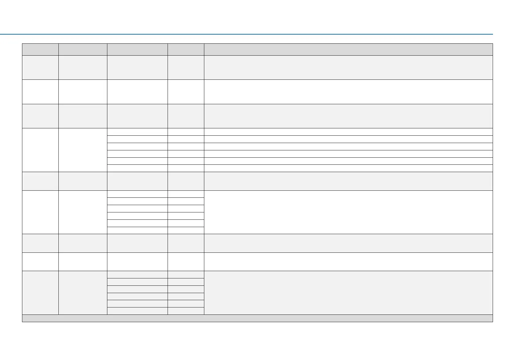
Display code Name
Possiblesengs/
value ranges
Keypad code Informaon
P400.18 Setp: Preset B0 Digital input 4 [14] Assignment of a trigger to the “Acvate preset (bit 0)” funcon.Bit with the value 20 for the bit-coded selecon and acvaon of a congured
setpoint (preset value).
Trigger = FALSE: Bit = “0”.
Trigger = TRUE: Bit = “1”.
P400.19 Setp: Preset B1 Digital input 5 [15] Assignment of a trigger to the “Acvate preset (bit 1)” funcon.Bit with the value 21 for the bit-coded selecon and acvaon of a congured
setpoint (preset value).
Trigger = FALSE: Bit = “0”.
Trigger = TRUE: Bit = “1”.
P400.20 Setp: Preset B2 Not connected [0] Assignment of a trigger to the “Acvate preset (bit 2)” funcon.Bit with the value 22 for the bit-coded selecon and acvaon of a congured
setpoint (preset value).
Trigger = FALSE: Bit = “0”.
Trigger = TRUE: Bit = “1”.
P420.01 Relay funcon Running [50] TRUE if inverter and start are enabled and output frequency > 0.2 Hz. Otherwise FALSE.
Readyforoperaon [51] TRUE if inverter is ready for operaon (no error acve, no STO acve and DC-bus voltage ok). Otherwise FALSE.
Operaon enabled [52] TRUE if inverter and start are enabled. Otherwise FALSE.
Stop acve [53] TRUE if inverter is enabled and motor is not started and output frequency = 0.
Error acve [56] TRUE if error is acve. Otherwise FALSE.
Device warning acve [58] TRUE if warning is acve. Otherwise FALSE.
P420.02 DO1 funcon Release brake [115] Assignment of a trigger to digital output 1.
Trigger = FALSE: X3/DO1 set to LOW level.
Trigger = TRUE: X3/DO1 set to HIGH level.
P430.01 AI1 input area 0...10VDC [0] Denion of the input range.
0 ... 5 VDC [1]
2 ... 10 VDC [2]
-10 ... +10 VDC [3]
4 ... 20 mA [4]
0 ... 20 mA [5]
P430.02 AI1 freq @ min - 1000.0 ... 0.0 ... 1000.0 Hz Denion of the seng range for AI1.
• Direcon of rotaon according to sign.
• Standard setpoint source for operang mode is selected in P201.01.
P430.03 AI1 freq @ max 50.0 Hz * | 60.0 Hz * Denion of the seng range for operang mode “MS: Velocity mode”.
• Direcon of rotaon according to sign.
• Standard setpoint source for operang mode is selected in P201.01.
P440.01 AO1 output area Disabled [0] Denion of the output range.
0...10VDC [1]
0 ... 5 VDC [2]
2 ... 10 VDC [3]
4 ... 20 mA [4]
0 ... 20 mA [5]
Defaultseng=boldprint|*Defaultsengisdevice-dependent

 Loading...


