5-4
DISASSEMBLY AND ADJUSTMENT
A. OUTER CASE REMOVAL
1) Disconnect the power supply cord from the outlet.
2) Remove the screws from the rear and both side of the case.
The outer case must be moved backward to be lifted off.
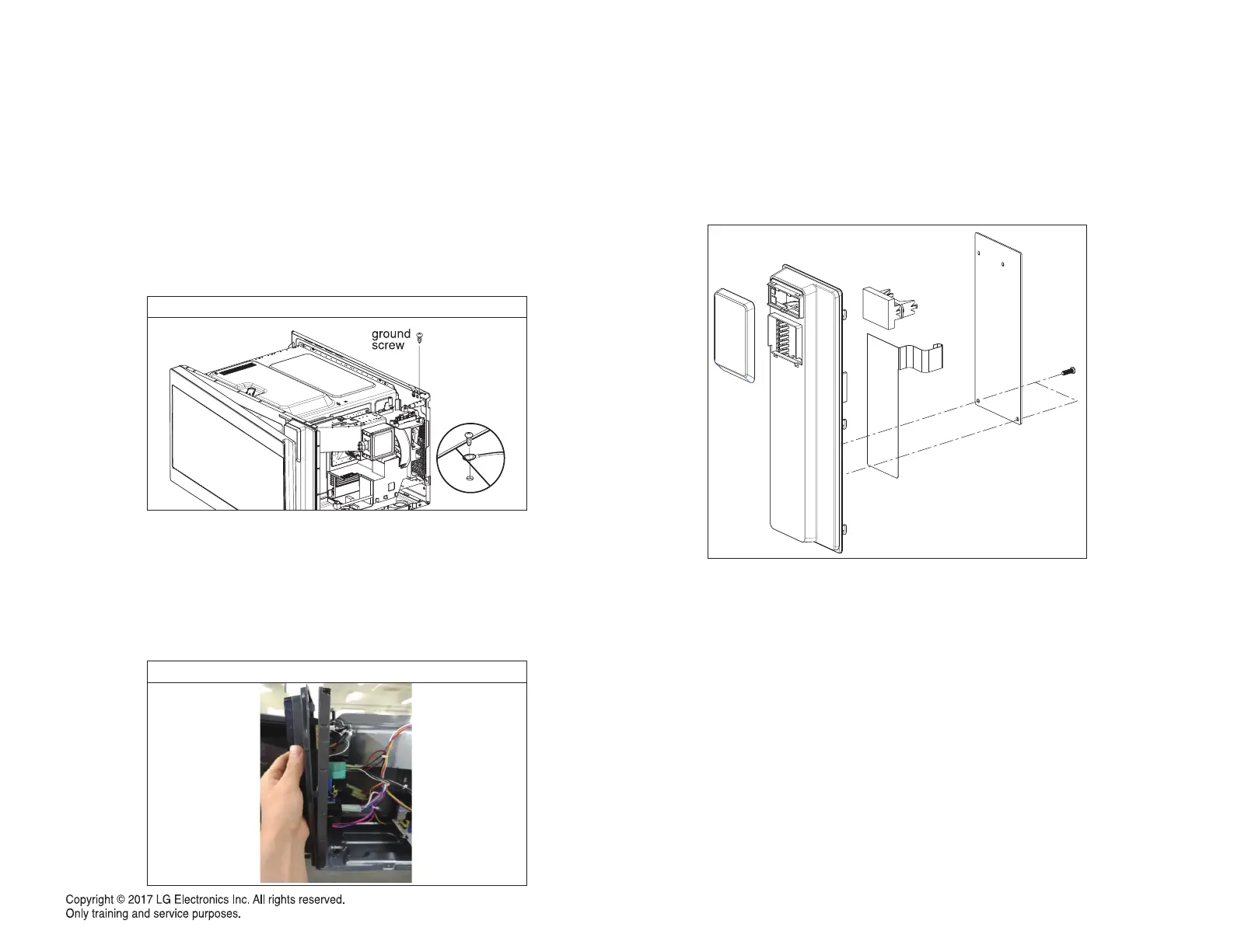
B. POWER SUPPLY CORD
1) Remove the outer case.
2) Disconnect two terminals and remove one screw of the ground terminal.
C. CONTROL PANEL ASSEMBLY
1) Open the door.
2) Disconnect the lead wire from RELAY and all connectors of the PCB SUB
ASSEMBLY.
3) Remove one screw on top and behind control panel and Lift up and pull out
control panel assembly carefully from the cavity.
D. PCB ASSEMBLY REMOVAL
1) Remove the control panel assembly from the cavity. (Refer to control panel
assembly removal on previous step.)
2) Remove screws which hold the PCB SUB ASS ’Y to the control panel.
Remove the screw
Lift up and pull out control panel
 Loading...