55
Wiring
Due to our policy of continuous product innovation, some specifications may change without notification.
©LG Electronics U.S.A., Inc., Englewood Cliffs, NJ. All rights reserved. “LG” is a registered trademark of LG Corp.
MULTI
F
MAX
MULTI
F
If ring terminals or spade clips are not available, then:
• Do not terminate different gauge wires to the power terminal block. Slack in the wiring may generate heat and fire.
•
Do not over tighten the connections; overtightening may damage the terminals.
• When terminating wires of the same thickness, follow the instructions demonstrated in the illustrations below.
• )LUPO\DWWDFKWKHZLUHVHFXUHLQDZD\WRSUHYHQWH[WHUQDOIRUFHVIURPEHLQJLPSDUWHGRQWKHWHUPLQDOEORFN
• Use an appropriately sized screwdriver for tightening the terminals.
• If power wires are not properly terminated and firmly attached, there is risk of fire, electric shock, and physical injury or death.
• Never ground the shield of the communications cable to the indoor unit frame or other grounded entities of the building. Failure to
properly provide a National Electrical Code-approved earth ground can result in electric shock, physical injury or death.
• Never apply line voltage power to the communications cable terminal block. If contact is made, the PCBs may be damaged.
• Always include some allowance in the wiring length when terminating. Provide some slack to facilitate removing the electrical panels while
servicing.
:Copper Wire
Terminate multiple power wires of
the same gauge to both sides.
Do not terminate two wires on
one side.
Do not terminate different gauge
wires to a terminal block.
Figure 75: Proper and Improper Power Wiring Connections
WIRING
Power Wiring and Communications Cable Connections
1. Detach the outdoor unit control cover by loosening and removing the screws.
2. Remove the side panel and the conduit panel knockouts.
3. Draw the power wiring to the outdoor unit, and the power wiring / communications
cable (connecting cable) to the indoor units or BD unit (Multi F MAX systems only),
through field-supplied conduits. Ensure there is enough length to connect the wir-
ing / cables to the terminals on the outdoor unit. Secure the conduit to the outdoor
unit using a field-supplied lock nut on the interior of the outdoor unit frame.
4. Properly connect the power wiring, and the power wiring / communications cable
(connecting cable) to the correct terminals. Refer to the outdoor unit wiring
diagram.
5. To provide strain relief, (separately) secure the power wiring and the power wiring
/ communications cable (connecting cable) to the outdoor unit with the factory-sup-
plied clamps (up to 35 lbs.). Zip ties can also be used to hold all wiring / cables in
place.
6. Re-attach the outdoor unit cover control to the original position with the screws.
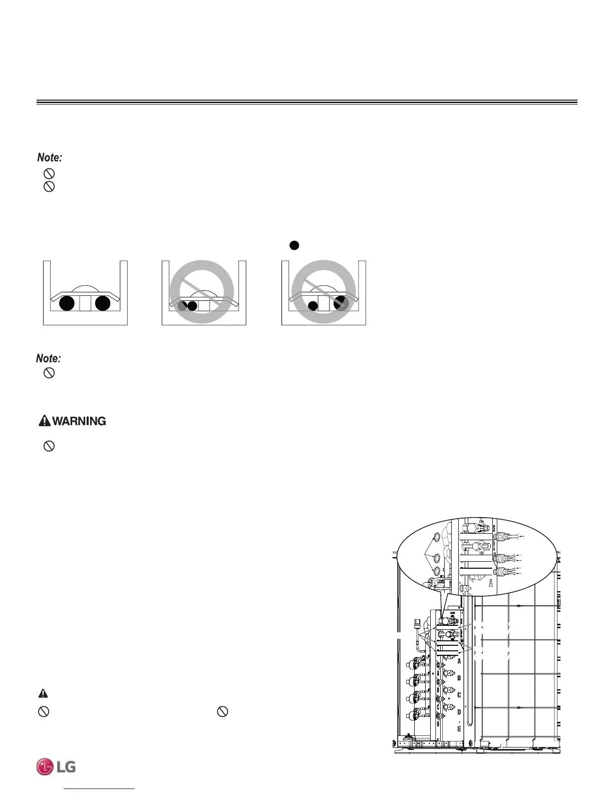
&RQQHFWLQJWKH3RZHU:LULQJ&RPPXQLFDWLRQV&DEOHWRWKH2XWGRRU8QLW
Figure 76: Connecting the Power Wiring / Communica-
tions Cables to the Outdoor Unit.
Power supply cabl
(1Ø, 208/230V)
Power Supply Cable
(1Ø, 208/230V)
Connecting cabl
(1Ø, 208/230V)
Connecting Cable
(1Ø, 208/230V)
Lock nut
(Field Supplied)
Indoor Unit A
Conduit
(Field Supplied)
Indoor Unit B
Indoor Unit C
Indoor Unit D
Conduit
Hole
Do not use damaged or loose power wiring. 'RQRWPRGLI\RUH[WHQGWKHRXWGRRU
unit’s power wiring randomly. Ensure that the power wiring will not be pulled nor weight
EHSODFHGRQWKHSRZHUZLULQJGXULQJRSHUDWLRQ7KHUHLVULVNRI¿UHHOHFWULFVKRFNDQG
physical injury or death.
DANGER
Outdoor Unit Wiring Connection Guidelines, continued.
 Loading...

