Due to our policy of continuous product innovation, some specications may change without notication.
©LG Electronics U.S.A., Inc., Englewood Cliffs, NJ. All rights reserved. “LG” is a registered trademark of LG Corp.
280 | MULTI F OUTDOOR UNIT
Multi F and Multi F MAX Heat Pump System Engineering Manual
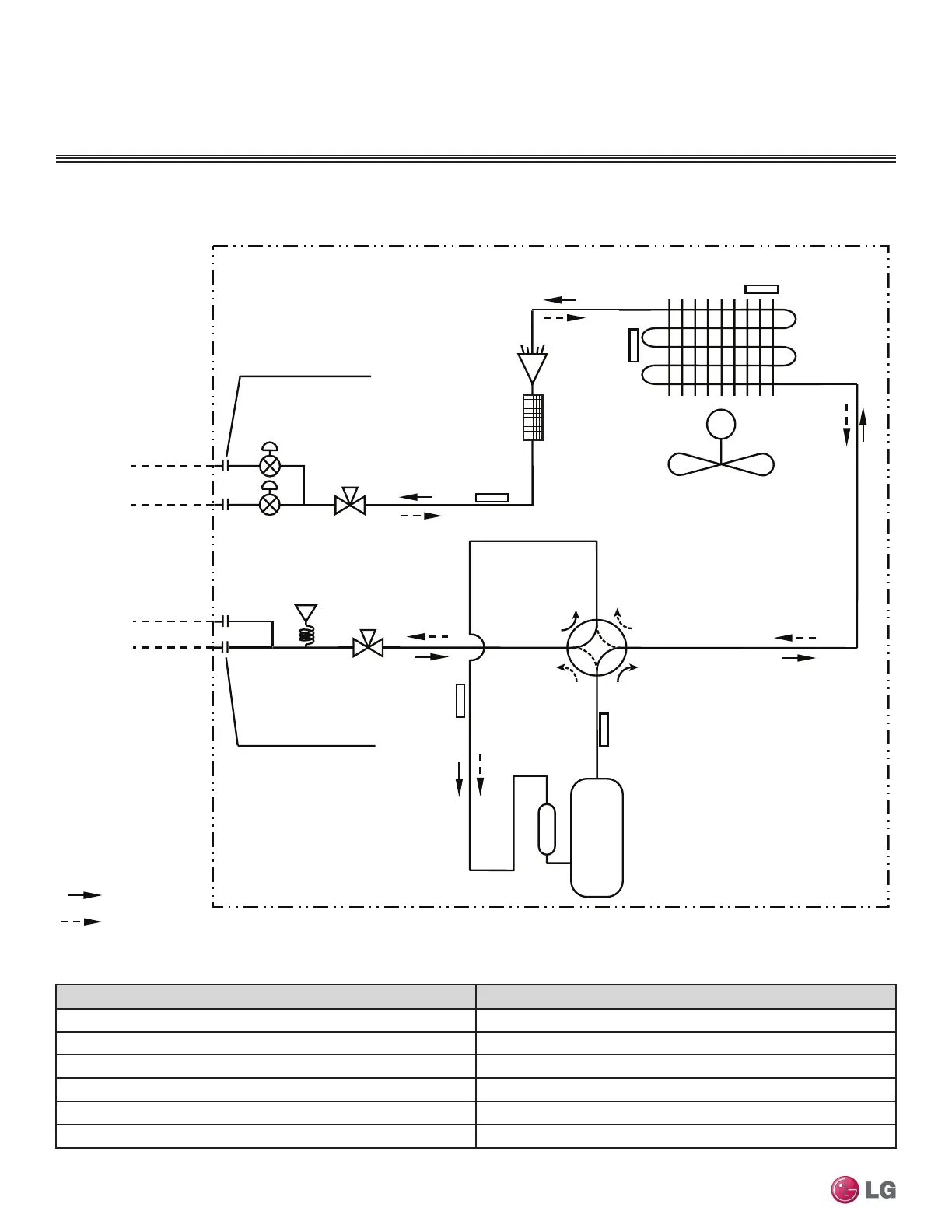
Figure 11: LMU18CHV Refrigerant Flow Diagram.
Description PCB Connector
Condenser Outlet Temperature Thermistor CN_C/PIPE
Condensing Temperature Thermistor CN_MID
Inlet Air Temperature Thermistor CN_AIR
Discharge Temperature Thermistor CN_DISCHARGE
Suction Temperature Thermistor CN_SUCTION
Pressure Sensor CN_H/PRESS
Table 274: LMU18CHV Thermistor Details.
M
Discharge
Temperature
Thermistor
Suction
Temperature
Thermistor
Inverter
Compressor
Electronic
Expansion
Valve
Condenser Outlet
Strainer
Temperature
Thermistor
Inlet Air
Temperature
Thermistor
Flare Connection
Flare Connection
Condensing
Temperature
Thermistor
ROOM A
ROOM A
ROOM B
: Cooling
: Heating
ROOM B
Main SVC V/V
Main SVC V/V
Pressure
Sensor
MULTI F OUTDOOR UNIT
Refrigerant Flow Diagram
 Loading...