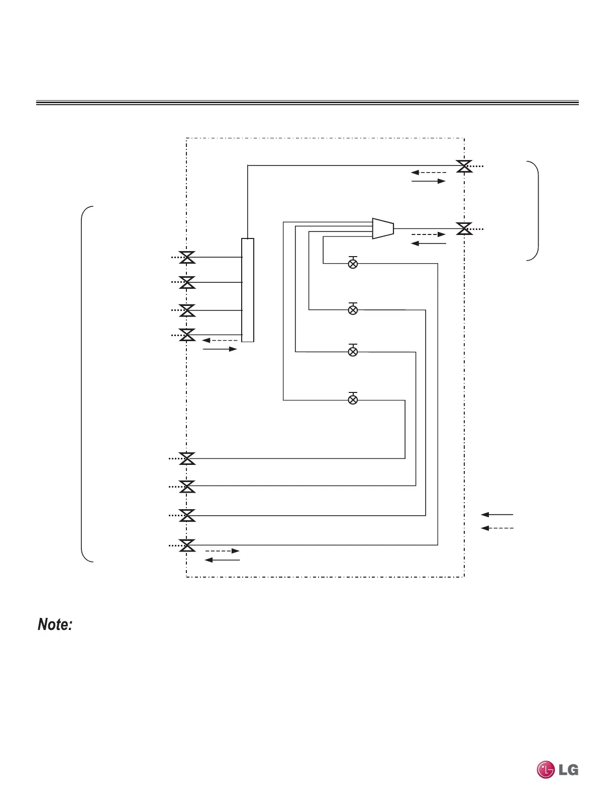
Figure 31:PMBD3620, PMBD3630, PMBD3640, PMBD3641 Refrigerant Flow Diagram.
MULTI F MAX BD UNIT
Refrigerant Flow Diagram
1. Flare connections for field piping installation.
2. Match the BD ports to the indoor unit and outdoor unit piping sizes. Use an adapter if the piping size does not match the piping size
of the connecting indoor unit.
3. EEV: Electronic Expansion Valve
4. PMBD3620 BD Unit supplied with "A, B".
PMBD3630 BD Unit supplied with "A, B, C".
PMBD3640 and PMBD3641 BD Units supplied with "A, B, C, D".
Main gas
piping
(
Ø
3/4)
Refrigerant flow
D Liquid (Ø1/4)
C Liquid (Ø1/4)
B Liquid (Ø1/4)
A Liquid (Ø1/4)
D Gas (Ø3/8)
*PMBD3641
D Gas: Ø5/8
*PMBD3641
D Liquid: Ø3/8
C Gas (Ø3/8)
Cooling
Heating
Main liquid
piping
(
Ø
3/8)
To
Outdoo
Unit
To
Indoor
Units
EEV-C
EEV-B
EEV-A
EEV-D
B Gas (Ø3/8)
A Gas (Ø3/8)
Unit: inch
Due to our policy of continuous product innovation, some specications may change without notication.
©LG Electronics U.S.A., Inc., Englewood Cliffs, NJ. All rights reserved. “LG” is a registered trademark of LG Corp.
336 | BD UNIT
Multi F and Multi F MAX Heat Pump System Engineering Manual
 Loading...