11
ENGLISH
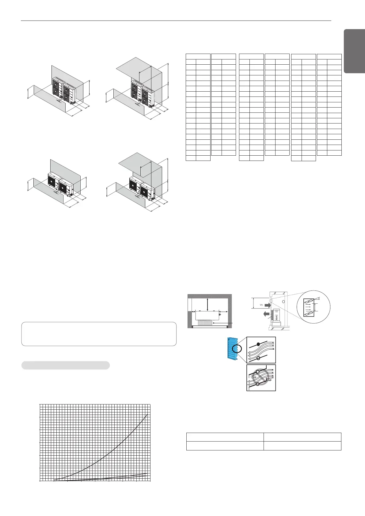
[Unit:mm]
2. Collective installation
H
L
350 or
more
1 500 or
more
100 or more
100 or more
500 or less
500 or less
more
1 000 or
H
L
350 or
more
1 500 or
more
100 or more
100 or more
500 or less
500 or less500 or less500 or less
L ≤ HL ≤ H
L
H
1 500 or
more
300 or
more
100 or
more
100 or
more
100 or100 or
moremore
100 or
more
500 or
less
500 or
less
1 000 or
more
L
H
1 500 or
more
300 or
more
100 or
more
100 or100 or
moremore
100 or
more
100 or
more
500 or
less
500 or500 or
lessless
500 or
less
L ≤ HL ≤ H
Seasonal wind and cautions in winter
• Sufficient measures are required in a snow area or severe cold area
in winter so that product can be operated well.
• Get ready for seasonal wind or snow in winter even in other areas.
• Install a suction and discharge duct not to let in snow or rain.
•
Install the outdoor unit not to come in contact with snow directly. If
snow piles up and freezes on the air suction hole, the system may
malfunction. If it is installed at snowy area, attach the hood to the
system.
• The raised support platform must be high enough to allow the unit to
remain above possible snow drifts, and must be higher than the
maximum anticipated snowfall for the location.
• Where snow accumulated on the upper part of the Outdoor Unit by
more than 10 cm, always remove snow for operation.
- Don't install the suction hole and discharge hole of the Outdoor
Unit facing the seasonal wind.
Secure minimum intake area
When the intake area is not secured can efficiency drop and products
may not be operating.
• Minimum intake area (For reference)
Air guide work
In case of out door unit is located outdoor cabin of apartment or flats,
then the efficiency can drop and system pressure increases thus finally
damaging the compressor or other components in the system by heat
short circuit.
• Do not use bended louver. It disturbs the air circulation.
• The opening ratio is at least 80 %.
• Louver angle is 0-20 degree.
• Louver pitch will be as more than 100 mm.
• If you have a insect control net, consider the shielded area and static
pressure loss.
• Check the static pressure range of outdoor unit fan.
Then, install air guide in the range of static pressure.
System(HP) 3, 4, 5, 6
Minimum intake area (m
2
) 0.7
300 mm or more
Air guide
Air guide duct
Less than
20 degrees
Louver pitch
100 mm or more
Wind speed : Vs ≤ 1.5 m/s
Intake
area
150 mm or
more
350 mm
or more
Less than
20 degrees
Louver pitch
100 mm or more
- The appliance shall be installed, operated and stored in a room with a floor
area larger than the minimum area.
- Use the graph of table to determine the minimum area.
- m : Total refrigerant amount in the system
- Total refrigerant amount : factory refrigerant charge + additional refrigerant amount
- Amin : minimum area for installation
Minimum floor area (for R32)
0
100
200
300
400
500
600
Amin (m
2
)
m (kg)
0 1.224 2 3 4 5 6 7 8
Floor standing
Wall mounted
Ceiling mounted
Floor location
m (kg) Amin (m
2
)
< 1.224 -
1.224 12.9
1.4 16.82
1.6 21.97
1.8 27.80
2 34.32
2.2 41.53
2.4 49.42
2.6 58.00
2.8 67.27
3 77.22
3.2 87.86
3.4 99.19
3.6 111.20
3.8 123.90
4 137.29
4.2 151.36
4.4 166.12
Floor location
m (kg) Amin (m
2
)
4.6 181.56
4.8 197.70
5 214.51
5.2 232.02
5.4 250.21
5.6 269.09
5.8 288.65
6 308.90
6.2 329.84
6.4 351.46
6.6 373.77
6.8 396.76
7 420.45
7.2 444.81
7.4 469.87
7.6 495.61
7.8 522.04
Wall mounted
m (kg) Amin (m
2
)
< 1.224 -
1.224 1.43
1.4 1.87
1.6 2.44
1.8 3.09
2 3.81
2.2 4.61
2.4 5.49
2.6 6.44
2.8 7.47
3 8.58
3.2 9.76
3.4 11.02
3.6 12.36
3.8 13.77
4 15.25
4.2 16.82
4.4 18.46
Wall mounted
m (kg) Amin (m
2
)
4.6 20.17
4.8 21.97
5 23.83
5.2 25.78
5.4 27.80
5.6 29.90
5.8 32.07
6 34.32
6.2 36.65
6.4 39.05
6.6 41.53
6.8 44.08
7 46.72
7.2 49.42
7.4 52.21
7.6 55.07
7.8 58.00
Ceiling Mounted
m (kg) Amin (m
2
)
< 1.224 -
1.224 0.956
1.4 1.25
1.6 1.63
1.8 2.07
2 2.55
2.2 3.09
2.4 3.68
2.6 4.31
2.8 5.00
3 5.74
3.2 6.54
3.4 7.38
3.6 8.27
3.8 9.22
4 10.21
4.2 11.26
4.4 12.36
Ceiling Mounted
m (kg) Amin (m
2
)
4.6 13.50
4.8 14.70
5 15.96
5.2 17.26
5.4 18.61
5.6 20.01
5.8 21.47
6 22.98
6.2 24.53
6.4 26.14
6.6 27.80
6.8 29.51
7 31.27
7.2 33.09
7.4 34.95
7.6 36.86
7.8 38.83
- U60A
- U36A
[Unit:mm]

 Loading...