29
ENGLISH
Display Title Cause of Error
Indoor unit related error
0 1 -
Air temperature sensor of indoor unit
Air temperature sensor of indoor unit is open or short.
0 2 -
Inlet pipe temperature sensor of indoor unit
Inlet pipe temperature sensor of indoor unit is open or short.
0 3 -
Communication error : wired remote controller
÷
indoor unit
Failing to receive wired remote controller signal in indoor unit PCB
0 4 -
Drain pump
Malfunction of drain pump
0 5 -
Communication error : outdoor unit
÷
indoor unit
Failing to receive outdoor unit signal in indoor unit PCB
0 6 -
Outlet pipe temperature sensor of indoor unit
Outlet pipe temperature sensor of indoor unit is open or short.
0 9 -
Indoor EEPROM Error
In case when the serial number marked on EEPROM of Indoor unit is 0 or
FFFFFF.
1 0 -
Poor fan motor operation
Disconnecting the fan motor connector/Failure of indoor fan motor lock
Outdoor unit related error
2 1 *
Outdoor Unit Inverter Compressor IPM Fault
Outdoor Unit Inverter Compressor Drive IPM Fault
2 2 *
Inverter Board Input Over Current(RMS) of Outdoor
Unit
Outdoor Unit Inverter Board Input Current excess (RMS)
2 3 *
Outdoor Unit Inverter Compressor DC link Low Voltage
DC charging is not performed at Outdoor Unit after starting relay turn on.
2 4 *
Outdoor Unit High Pressure Switch
System is turned off by Outdoor Unit high pressure switch.
2 5 *
Outdoor Unit Input Voltage High/ Low Voltage
Outdoor Unit input voltage is over 487 V or below 270 V.
2 6 *
Outdoor Unit Inverter Compressor Start Failure
The First Start Failure by Outdoor Unit Inverter Compressor Abnormality
2 9 *
Outdoor Unit Inverter Compressor Over Current
Outdoor Unit Inverter Compressor Fault OR Drive Fault
* Refer to the Indoor manual for some Indoor Error code.
Self-Diagnosis Function
Error Indicator
- This function indicates types of failure in self-diagnosis and occurrence of failure for air condition.
- Error mark is displayed on display window of indoor units and wired remote controller, and 7-segment LED of outdoor unit control board as
shown in the table.
- If more than two troubles occur simultaneously, lower number of error code is first displayed.
- After error occurrence, if error is released, error LED is also released simultaneously.
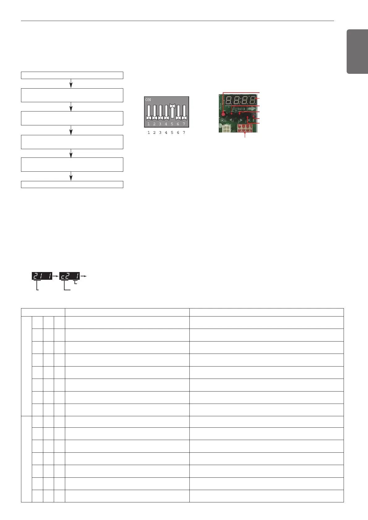
Error Display
1st, 2nd, 3rd LED of 7-segment indicates error number, 4th LED indicates unit number.
Ex)
Error No. of Compressor
Error No.
Error No. of Unit
Repeat
Master unit PCB DIP switch on : No.5
Select the mode using ‘▶’, ‘◀’ Button :
“Func” Push the ‘●’ button
Select the Function using ‘▶’, ‘◀’ Button :
“Fn25” Push the ‘●’ button
Select the Option using ‘▶’, ‘◀’ Button :
“hEAt” Push the ‘●’ button
Heating priority operation is set
Select the Option using ‘▶’, ‘◀’ Button :
“on” , “oFF” Push the ‘●’ button
Priority Heating Operation
This is the function that gives priority to the hot water supply operation (heating) for the model that cannot simultaneously operate heating and
cooling.
This function enables the appliance to supply hot water and operate indoor cooling by alternatevely heating using hydrokit and cooling operation.
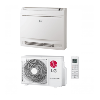
Mode setting method
Setting the function
Select the mode/function/option/value using ‘▶’, ‘◀’ Button and
confirm that using the ‘●’ button after DIP switch No.5 is turned on.
DIP SWITCH
7-Segment
SW01C ( Ɨ: confirm)
SW02C ( ȭ: backward)
SW04C ( X : cancel)
SW01D (reset)
SW03C ( ȯ: forward)
 Loading...