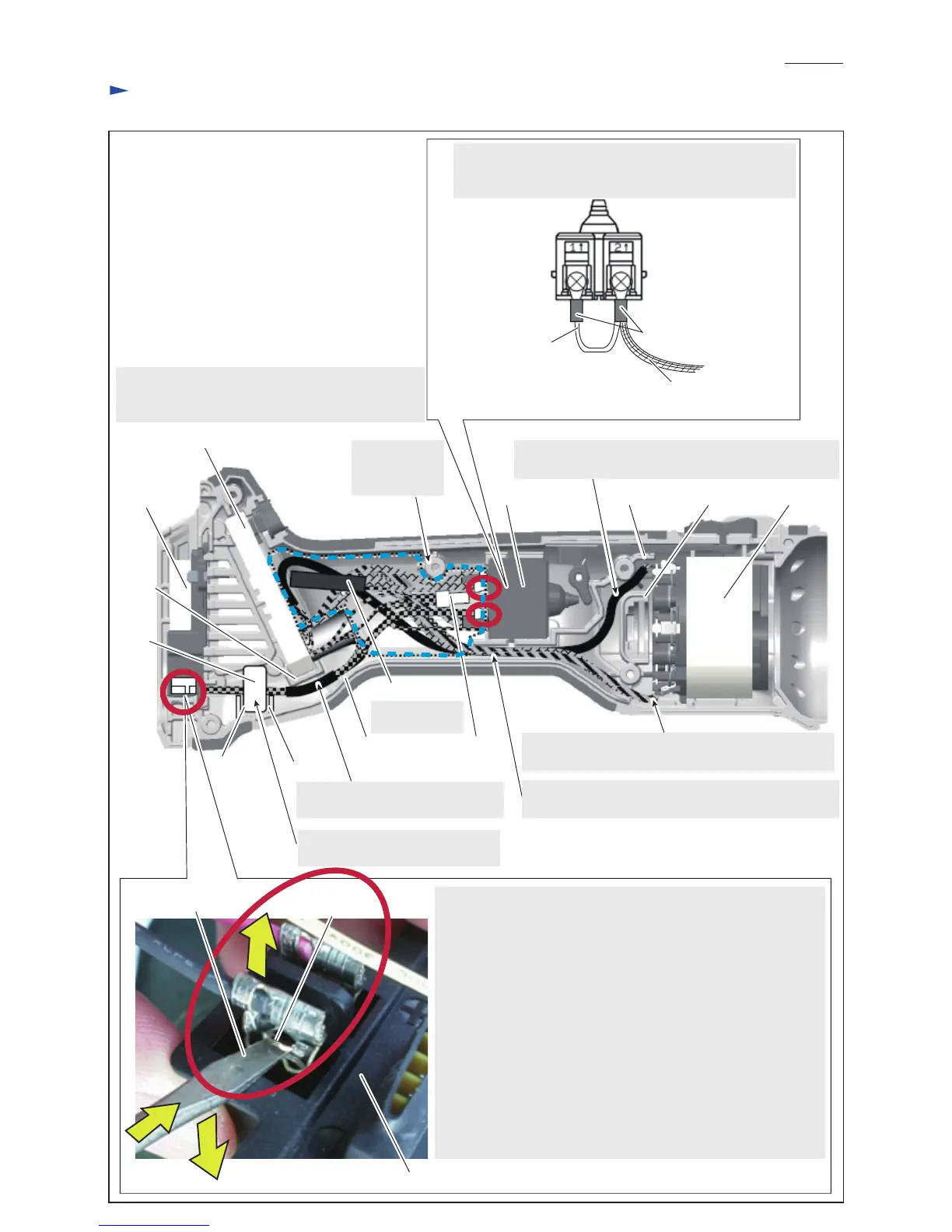
Wiring diagram
P 12/ 14
Fig. D-2
Switch
Controller
Connect Lead wire (white) and Lead wire (orange) to
Switch with Insulated terminal.
Be careful about the directions of the insulated terminals.
Insulated terminals
Battery
terminal Stator completeRib B
Rib D
Rib F
Projection on
Flag terminal
Rib E
Rib C Connector 2-SD
Resistor unit
Line
filter
Rib A
When Line filter is used, insert it
between Rib E and Rib F.
Important:
Three Flag teminals and two straight teminals (circled by red)
have a lock structure, that enables you to remove the flag/ straight
terminals from the tab of Battery terminal with ease.
While pushing the projection of the flag/ straight teminal with
a slotted screwdriver to release the lock, pry off the flag/ straight
terminal from the tab of Battery terminal as shown left.
Note: Check whether flag/ straight terminals have a lock structure
before disassembly as follows:
• Find the projection on flag/ straight terminals.
• Swing flag/ straight terminals slightly and gently to
feel a little backlash due to the lock structure.
Never force to pull any flag/ straight terminals !
Connect flag/ straight terminals onto the tabs of Battery terminals
until you can hear a tiny click sound.
Lead wires from Terminal must be
routed between Rib C and Rib D.
Thick Lead wire from Stator complete must be bent
to prevent pinching between Housing L and R.
Lead wires covered with a tube from Stator complete
must be placed under Thick lead wire.
Lead wires covered with a tube from Stator complete
must be routed between Rib A and Rib B.
Do not put any
Lead wires on
this boss.
Place Resistor unit and Connector 2-SD in the area
circled by a blue broken line. Connector 2-SD must
not be placed on/ under Noise suppressor (if used).
Be sure to use
Resistor unit.
Lead wire (white)
between Terminal 1
and Terminal 2
Lead wire (orange) from Controller
Battery terminal
Slotted screwdriver

 Loading...