Repair
P 9/ 14
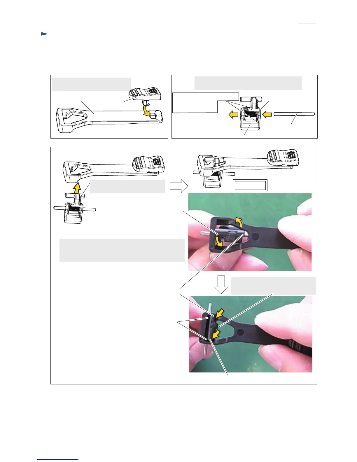
Refer to the following and next pages. (Figs. 25, 26, 27, and 28)
Fig. 25 Fig. 26
Insert the hook of Switch knob into
the square hole of Switch lever
Protrude the bar of Lever from
the triangle hole of Switch lever.
Turn the bar of Lever counterclockwise to place
the long bar end and the short bar end onto
the depressions on the triangle corners of Switch lever.
[3] DISASSEMBLY/ASSEMBLY
[3]-5. Assembling of Switch knob and Switch lever
Switch lever Switch knob
The ends of Torsion spring 2
must be placed on
these positions.
Fig. 27
Set Torsion spring 2 in place of Lever, and then
pass Pin 2 through the holes of Lever.
Lever
Pin 2
Torsion spring 2
Upper view
Long bar end of Lever
The curve of Lever must be faced
toward the center of the triangle hole.
Long bar end of Lever
Depressions on the triangle
corners of Switch lever
Short bar end of Lever
 Loading...