7 ENGLISH
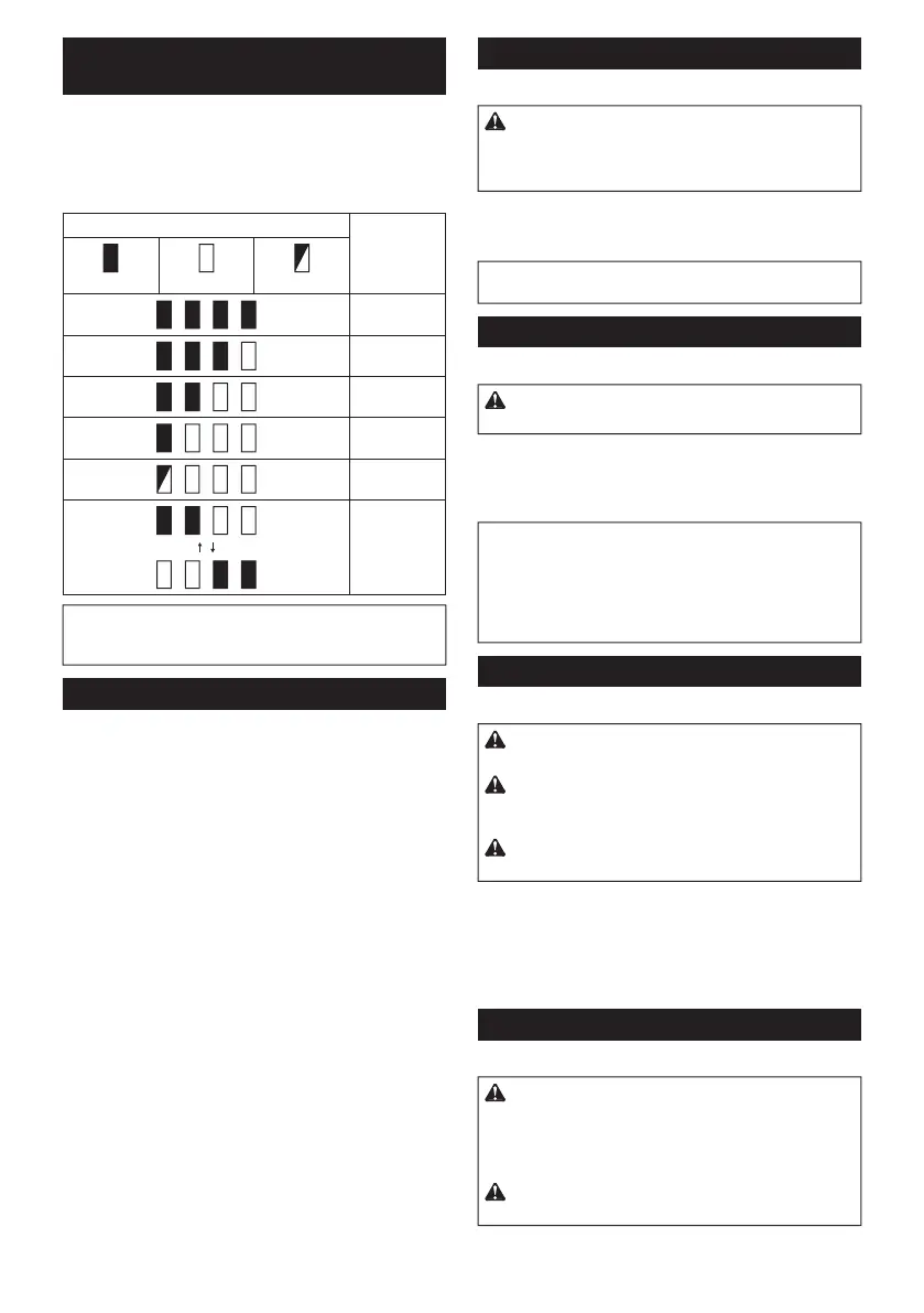
Indicating the remaining battery
capacity
Only for battery cartridges with the indicator
Fig.2: 1. Indicator lamps 2.
-
light up for a few seconds.
Indicator lamps Remaining
capacity
Lighted Blinking
75% to 100%
50% to 75%
25% to 50%
0% to 25%
Charge the
may have
malfunctioned.
NOTE: Depending on the conditions of use and the
from the actual capacity.
Tool / battery protection system
-
Overload protection
This protection works when the tool is operated in a
-
-
turn the tool on to restart.
Overheat protection
-
Overdischarge protection
Switch action
Fig.3: 1. Switch trigger
CAUTION: Before installing the battery car-
tridge into the tool, always check to see that the
switch trigger actuates properly and returns to
the "OFF" position when released.
To start the tool, simply pull the switch trigger. Tool
trigger. Release the switch trigger to stop.
NOTE: The tool automatically stops if you keep pull-
Lighting up the front lamp
Fig.4: 1. Lamp
CAUTION: Do not look in the light or see the
source of light directly.
The lamp goes out approximately 10 seconds after
releasing the switch trigger.
NOTE:
When the tool is overheated, the tool stops auto-
NOTE:
the lamp. Be careful not to scratch the lens of lamp, or
it may lower the illumination.
Reversing switch action
Fig.5: 1. Reversing switch lever
CAUTION: Always check the direction of
rotation before operation.
CAUTION:
Use the reversing switch only after
the tool comes to a complete stop. Changing the direc-
CAUTION:
When not operating the tool, always
set the reversing switch lever to the neutral position.
This tool has a reversing switch to change the direction
of rotation. Depress the reversing switch lever from the
-
terclockwise rotation.
When the reversing switch lever is in the neutral posi-
Speed change
Fig.6: 1. Speed change lever
CAUTION: Always set the speed change lever
fully to the correct position. If you operate the
tool with the speed change lever positioned halfway
damaged.
CAUTION: Do not use the speed change lever
while the tool is running.

 Loading...