19 ENGLISH
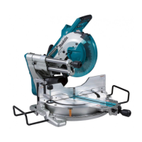
Adjusting the miter angle
Fig.24: 1. Turn base 2. Lock lever 3. Miter scale
4. Pointer 5. Grip
1. Loosen the grip counterclockwise.
2.
angle of the turn base. Use the pointer and the miter
scale as a guide.
3.
CAUTION: After changing the miter angle,
always secure the turn base by tightening the grip
NOTICE: When turning the turn base, be sure to
raise the handle fully.
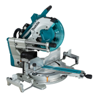
Adjusting the bevel angle
the tool counterclockwise.
Fig.25: 1. Lever 2. Release button
To tilt the blade to the left, hold the handle and tilt the
carriage. Use the bevel scale and the pointer as a
the arm.
Fig.26: 1. Pointer 2. Bevel scale 3. Arm
To tilt the blade to the right, hold the handle and tilt the
carriage to the left slightly, and push the release button.
With the release button pressed, tilt the saw blade to
the right. Then tighten the lever.
CAUTION: After changing the bevel angle,
always secure the arm by tightening the lever
clockwise.
NOTICE: When tilting the saw blade be sure the
handle is fully raised.
NOTICE: When changing bevel angles, be
sure to position the kerf boards appropriately
as explained in the "Positioning kerf boards"
section.
Adjusting the lever position
If the lever does not provide full tightening in course of
time, change the position of the lever. The lever can be
repositioned at every 30° angle.
Loosen and remove the screw that secures the lever.
Remove the lever and install it again so that it points
slightly above the horizontal. Then, tighten the lever
Fig.27: 1. Lever 2. Screw
Switch action
WARNING: Before installing the battery car-
tridge on the tool, always check to see that the
switch trigger actuates properly and returns to
the "OFF" position when released. Operating a tool
with a switch that does not actuate properly can lead
WARNING: Do not use a lock with a shank or
cable any smaller than 6.35 mm (1/4") in diameter.
A smaller shank or cable may not properly lock the
WARNING: NEVER use tool without a fully
operative switch trigger. Any tool with an inoper-
ative switch is HIGHLY DANGEROUS and must be
repaired before further usage or serious personal
WARNING: For your safety, this tool is equipped
unintended starting. NEVER use the tool if it runs
when you simply pull the switch trigger without
A switch in need of
repair may result in unintentional operation and seri-
center for proper repairs BEFORE further usage.
WARNING:
by taping down or some other means. A switch with
NOTICE: Do not pull the switch trigger hard
This can
cause switch breakage.
To prevent the switch trigger from being accidentally
Release the switch trigger to stop.
A hole is provided in the switch trigger for insertion of a
Fig.28: 1.2. Switch trigger 3. Hole
for padlock
ASSEMBLY
WARNING: Always be sure that the tool is
before working on the tool.
remove the battery cartridge may result in serious
Hex wrench storage
the hex wrench is needed it can be pulled out of the
wrench holder.
After using the hex wrench it can be stored by returning
it to the wrench holder.
Fig.29: 1. Wrench holder 2. Hex wrench

 Loading...