15
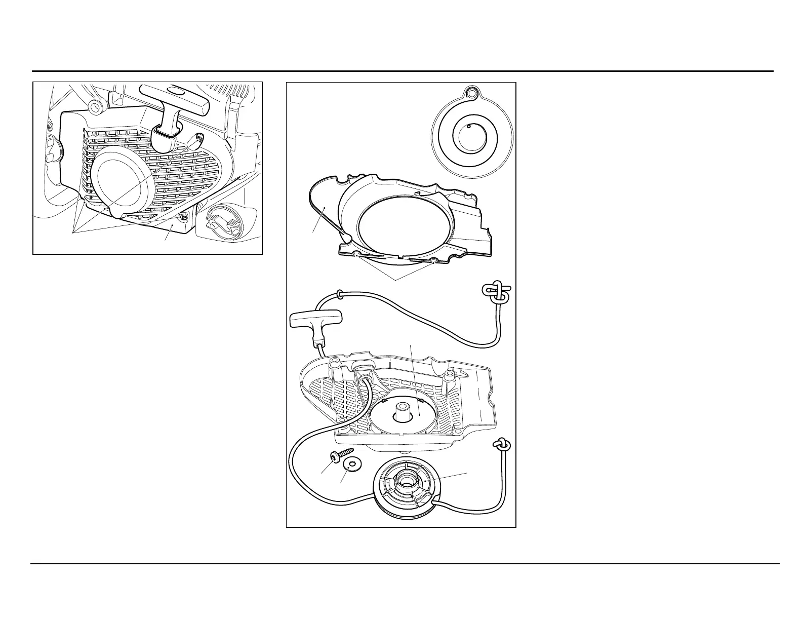
Knock the fan housing against a tabletop with
the entire contact surface of the hollow side, so
that the return spring cassette 8 pops out of the
fan housing.
Caution! The return spring can jump out of
the plastic cassette! Always wear protective
goggles and gloves!
If the spring pops out, put it back into the plastic
housing as shown in the schematic.
Assembly
Note: If installing a new return spring cassette,
grease it on the spring side.
Carefully insert the new return spring cassette 8
and press down until it engages. Lightly grease
the surface of the spring and spring cassette
(944.360.000).
Thread in a new starter cable (dia 3.5 mm /
1/8“, length 980 mm / 38.5“) as shown in the
illustration, tie a knot (as shown in the
illustration) in both ends, and tighten both knots.
Put on the cable drum 7 and turn it slightly until
the return spring engages.
Screw in the screw with washer.
Tension the return spring clockwise about 8 1/2
turns.
Place the air guide 3 in the fan housing and
make sure the two recesses 4 engage.
Position the fan housing 2 correctly on the saw,
press against it slightly, and pull the starter
handle until the starter catches.
Tighten screws 1.
Disassembly
Unscrew four screws 1.
Remove fan housing 2.
Remove air guide 3 from fan housing.
Detension the return spring.
Injury hazard! Unscrew screw 5 only after
detensioning the return spring!
Unscrew screw 5 and remove the washer 6.
Pull off the cable drum 7.
 Loading...