P 14/ 15
(1) Remove “Air filter, Carburetor, and Intermediate flange” as mentioned in [2]-10. (Figs. 22, 23, 24, and 25)
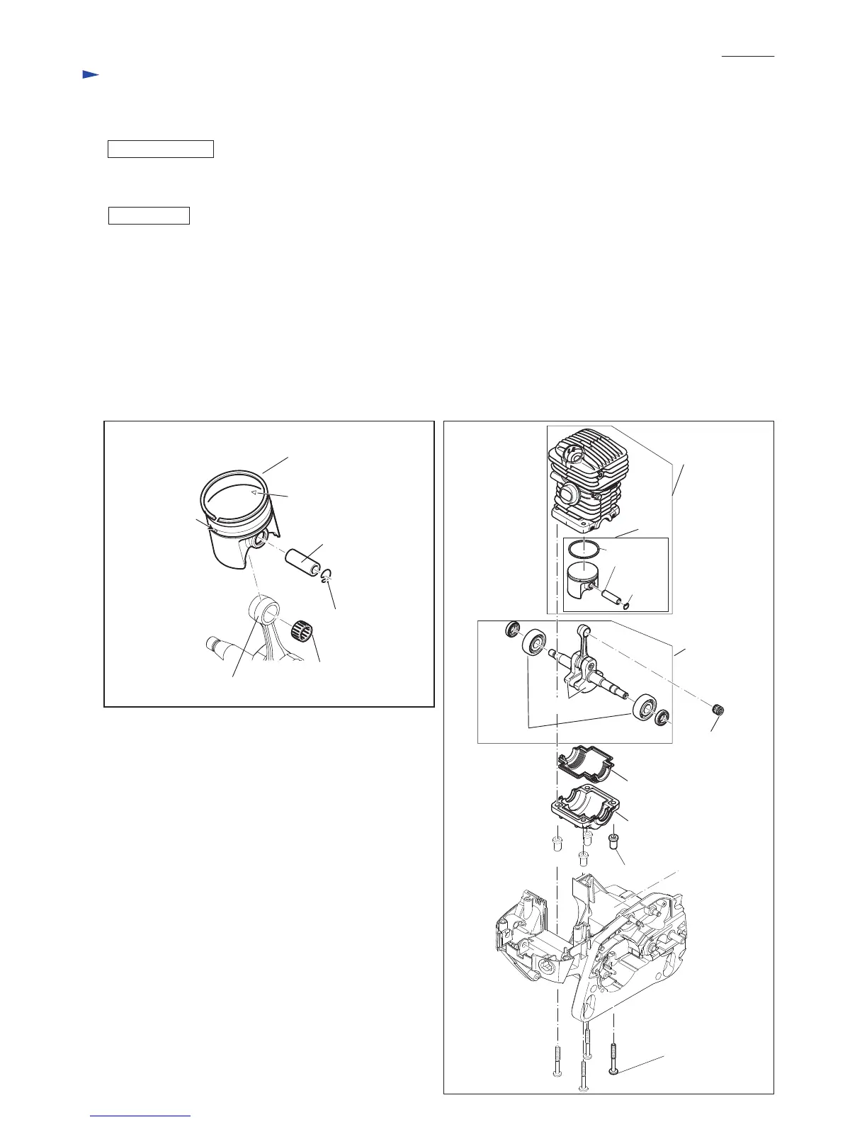
(2) Piston set can be separated from Crank shaft by removing Ring spring 8 from Piston with Long-nose pliers. (Fig. 38)
Note: Supply 2-stroke engine oil to Piston and the inside of Cylinder in advance.
Important: See Figs. 38 and 39.
• Set Piston in place with the arrow marking faced to Muffler side.
• Face the gap of Piston ring 38 to Carburetor side. Make sure that a small projection in Piston groove comes
in the gap of Piston ring 38.
• Ring spring 8 and Piston pin 8 have to be installed into Piston through Needle cage 810 and Crank shaft from
Guide bar side.
• Be sure to use New Gasket (Fig. 10) and New Crank case sealing.
• When replacing Ball bearing 6201, press-fit the inner ring portion to Crank shaft using the same size pipe
and a block for placing the counterweights without bending.
After the above steps, reverse the disassembling procedure of “DISASSEMBLING of [2]-11. Tank assembly.
Arrow marking
on Piston
Piston ring 38
Small projection
in the groove of
Piston
Ring spring 8
Piston pin 8
Piston ring 38
Ring spring 8
Piston pin 8
[Carburetor side]
[Guide bar side]
[Carburetor side]
[Guide bar side]
Repair
DISASSEMBLY
ASSEMBLY
[2] DISASSEMBLY/ ASSEMBLY
[2]-15. Cylinder, Piston
Fig. 38 Fig. 39
Needle cage 810
Crank shaft
Crank shaft set
Counterweights
Crank case sealing
Crank case underside
5x40 Hexalobular
tapping screw (4 pcs.)
(See Fig. 24.)
Bush 6 (4 pcs.)
Piston set
Cylinder
piston set
Needle cage 810
Ball bearing 6201
 Loading...