Internal cooling water system
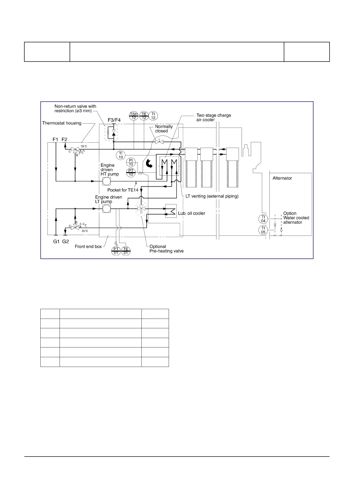
Figure 1: Diagram for internal cooling water system (for guidance only, please see the plant specific engine diagram)
Pipe description
F1 HT fresh water inlet DN 100
F2 HT fresh water outlet DN 100
F3 Venting to expansion tank DN 25
F4 HT fresh water for preheating DN 25
G1 LT fresh water inlet DN 100
G2 LT fresh water outlet DN 100
Table 1: Flange connections are standard according to DIN 2501
Description
The system is designed as a two string circuit with
four flange connections to the external centralized
cooling water system.
The engine is equipped with a self-controlling tem-
perature water circuit. This is a simple solution with
low installation costs, which also can be interesting
in case of repowering.
Low temperature circuit
The components for circulation and temperature
regulation are placed in the internal system.
The charge air cooler and the lubricating oil cooler
are situated in serial order. After the LT water has
passed the lubricating oil cooler, it is let to the ther-
mostatic valve and depending on the water temper-
ature, the water will either be re-circulated or led to
the external system.
The engine on the cooling water side only requires
fresh water between 10 and 40°C.
MAN Diesel & Turbo
3700203-1.0
Page 1 (2)
Internal cooling water system
B 13 00 6
L27/38S, L27/38
2015.04.23 - Tier II - two string
 Loading...