Compressed air system
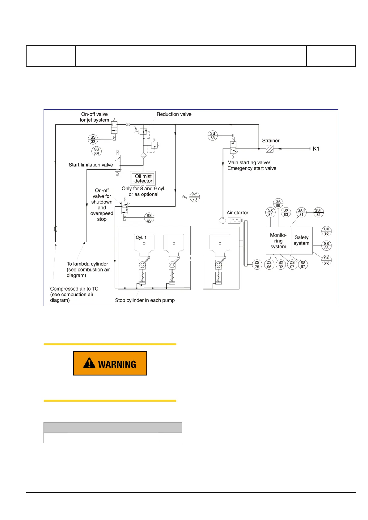
Figure 1: Diagram for 30 bar compressed air system (for guidance only, please see the plant specific engine diagram).
Air supply!
Air supply must not be interrupted when engine
is running
Pipe description
Pipe description
K1 Compressed air inlet DN 40
Table 1: Flange connections are standard according to DIN 2501
General
The compressed air system on the engine consists
of a starting system, starting control system and
safety system. Further, the system supplies air to
the jet system and the stop cylinders on each fuel
injection pump. On 8 and 9 cylinder engines air is
supplied to the oil mist detector through a reduction
valve.
The compressed air is supplied from the starting air
receivers (30 bar) to the engine.
To avoid dirt particles in the internal system, a
strainer equipped with a drain valve is mounted in
the inlet line to the engine.
Starting system
The engine is started by means of a built-on air
starter, which is a turbine motor with gear box,
safety clutch and drive shaft with pinion. Further,
there is a main starting valve.
MAN Diesel & Turbo
3700206-7.1
Page 1 (2)
Compressed air system
B 14 00 0
L27/38S, L27/38
2015.11.09 - Tier II, Stationary, Gali, Optional
 Loading...