SET-UP AND INSTALLATION 31000 LUFFING JIB OPERATOR MANUAL
4-76 Published 07-23-15, Control # 078-03
4
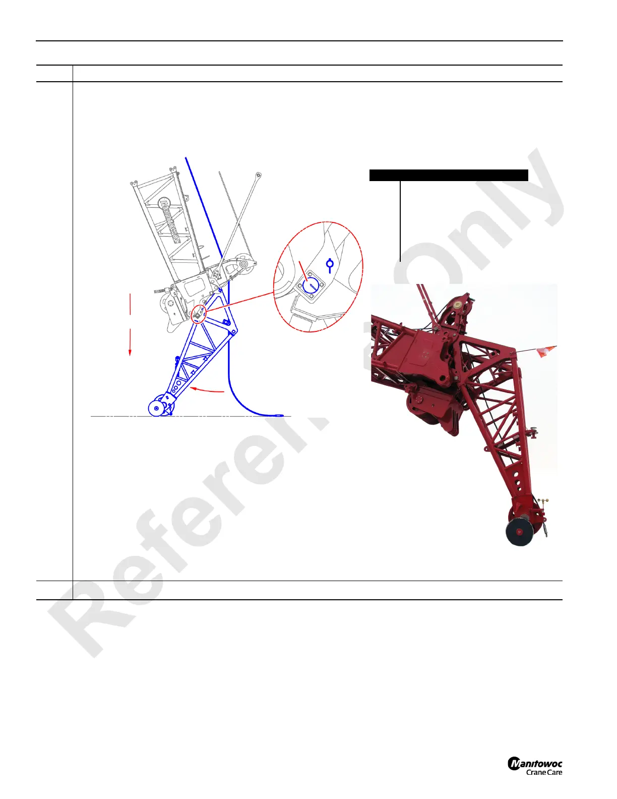
Information below from drawing A19443, Sheet 28:
• Slowly boom down as the upper boom point wheel (A) contacts the ground and rolls towards the crane.
• When the upper boom point (B) rotates into position against the load pins (C), reinstall the locking pins (D).
• As required, install aircraft warning flag (E), warning light (F), and wind speed indicator (G).
5
This completes the Method 2 upper boom point installation procedure.
Step Action
FIGURE 4-83
Item Description
A Upper boom point wheel.
B Upper boom point.
C Load pin.
D Locking pin.
E Aircraft warning flag.
F Warning light.
G Wind speed indicator.
Boom down
A
B
C
D
E
F
G

 Loading...


