SET-UP AND INSTALLATION 31000 LUFFING JIB OPERATOR MANUAL
4-20 Published 07-23-15, Control # 078-03
Assemble the Upper Half of the Main Strut
Step Action
19
Information below from drawing A19443, Sheet 12:
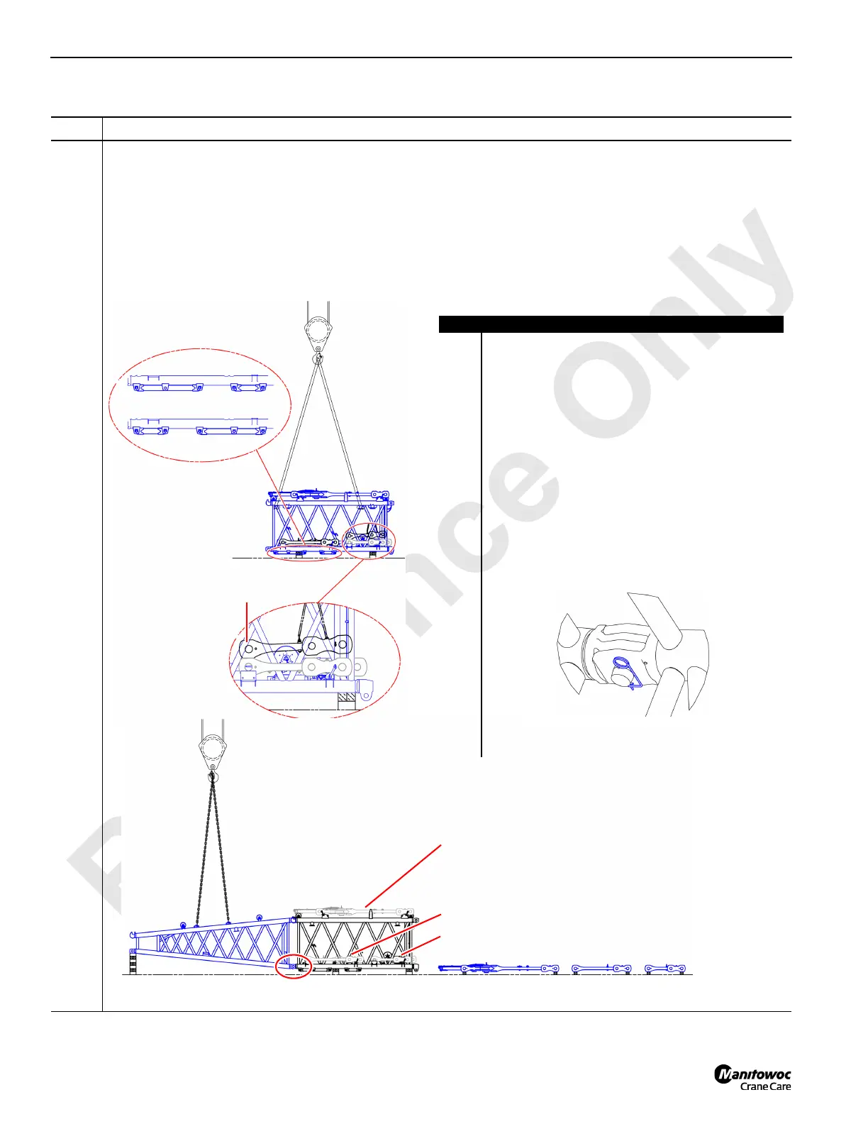
Use an assist crane (A) to assemble the upper half of the main strut:
• Block the main strut insert (B).
• Configure the support struts (C and D) based on the #90 boom length.
• For upcoming steps, note the short strap lifting points (E), removal (F), and shipment location (F and G).
• Remove the stowed jib backstay straps (I and J) and the jib backstay spreader (K) from the main strut insert (B).
• Attach the main strut transition insert (H) to the main strut insert (B) using safety pins (L).
FIGURE 4-20
A
B
C
D
E
F
E
G
A
BHKI
J
K (shipping position)
I (shipping position)
J (shipping position)
L
Item Description
A Assist crane.
B Main strut insert.
C Support strut configuration for 55 m (180.5 ft), 60 m
(196.9 ft), and 65 m (213.3 ft) #90 boom lengths.
D Support strut configuration for 70 m (229.7 ft), 75 m
(246.1 ft), 80 m (262.5 ft), 85 m (278.9 ft), 90 m (295.3
ft), 95 m (311.7 ft), 100 m (328.1 ft), and 105 m (344.5 ft)
#90 boom lengths.
E Short strap lifting points.
F Short strap removal and storage.
G Attach this end to insert first.
H Main strut transition insert.
I Jib backstay strap, 3.14 m (10.3 ft).
J Jib backstay strap, 2.19 m (7.2 ft).
K Jib backstay spreader.
L Insert joint with safety pin:
M Blocking — under the main strut transition insert to
necessary to maintain stability.
M

 Loading...


