Manitowoc Published 07-23-15, Control # 078-03 6-3
31000 LUFFING JIB OPERATOR MANUAL MAINTENANCE
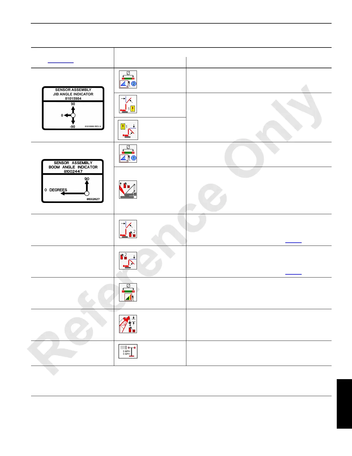
SENSOR MAINTENANCE
Sensor
(see Figure 6-1
for locations)
Maintenance
Possible Fault
1
Remedy
Jib angle indicator
Fault 64: Jib
angle sensor out
of range.
• Check sensor wiring. Perform an RCL/RCI calibration.
2
• Replace the sensor. See the 31000 Service Manual.
Fault 49: Jib
maximum up
angle.
• These fault icons indicate operational limits which are
not necessarily sensor malfunctions.
• However, if a sensor malfunction is suspected, first
perform an RCL/RCI calibration
2
.
• If sensor calibration fails to correct the fault, replace the
sensor. See the 31000 Service Manual.
Fault 50: Jib
maximum down
angle.
Boom angle indicator
Fault 63: Boom
angle sensor out
of range.
• Check sensor wiring. Perform an RCL/RCI calibration.
2
• Replace the sensor. See the 31000 Service Manual.
Fault 55: Boom
maximum up.
• This fault icon indicates an operational limit which is not
necessarily a sensor malfunction.
• However, if a sensor malfunction is suspected, first
perform an RCL/RCI calibration
2
.
• If sensor calibration fails to correct the fault, replace the
sensor. See the 31000 Service Manual.
Luffing jib maximum angle limit
switch
Fault 73: Jib
maximum up
switch.
• This fault icon indicates an operational limit which is not
necessarily a sensor malfunction.
• However, if a sensor malfunction is suspected, try
adjusting the sensor as described on page 7
.
Luffing jib minimum angle
switch
Fault 67: Jib
maximum down
switch.
• This fault icon indicates an operational limit which is not
necessarily a sensor malfunction.
• However, if a sensor malfunction is suspected, try
adjusting the sensor as described on page 4
.
Load links and load pins
Fault 42: RCL/
RCI sensor out
of range.
• Check sensor wiring. Perform an RCL/RCI calibration.
2
• If load sensor calibration fails to correct the fault, use
the RCL/RCI Diagnostics screen
2
to try to isolate the
faulty sensor. Then replace the sensor.
Block-up limit switch
Fault 60: Block-
up limit.
• This fault icon indicates an operational limit which is not
necessarily a sensor malfunction.
• However, if a sensor malfunction is suspected, see the
31000 Service Manual.
Wind speed indicator
Main Display
wind speed icon.
• There is no fault icon for the wind speed indicator.
• If a fault is suspected with the wind speed indicator,
replace the indicator. See the 31000 Service Manual.
NOTES:
1
Fault icons appear on the Main Display screen. See Folio 2207 for more information.
2
See Folio 2204 for more information.

 Loading...


