Manitowoc Published 07-23-15, Control # 078-03 4-7
31000 LUFFING JIB OPERATOR MANUAL SET-UP AND INSTALLATION
6
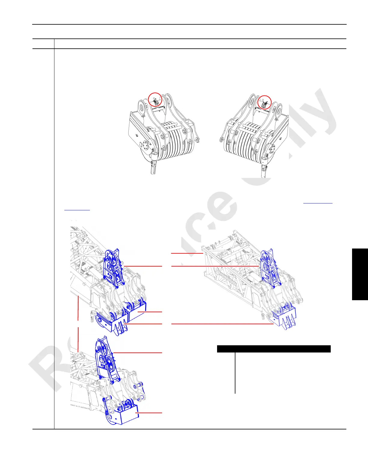
Information below from drawing A19443, Sheet 3:
Relocate the wire rope guide (C) and left (D) and right (E) boom point lower assemblies:
NOTE: In order to remove or attach the left (D) and right (E) boom point lower assemblies to the #90 boom top
(A), connect the ISO 46 hydraulic circuit of the Portable Power Unit to the hydraulic couplers (circled
below) of the lower assemblies:
• Relocate the #90 boom top (A) wire rope guide (C) to the #91 luffing jib top (B) as shown below.
• Attach wire rope guide (F) to the #90 boom top (A).
• Relocate the boom point right hand lower assembly (E) to the #91 luffing jib top (B) as shown in Figure 4-54
on
page 4-52
.
• Move the boom point left hand lower assembly (D) to the center of the #90 boom top (A) as shown below:
Step Action
Item Description
A #90 boom top.
B #91 luffing jib top.
C Wire rope guide (A18941).
D Boom point left hand lower assembly.
E Boom point right hand lower assembly.
F Wire rope guide (81011450).

 Loading...


