SET-UP AND INSTALLATION 31000 LUFFING JIB OPERATOR MANUAL
4-26 Published 07-23-15, Control # 078-03
26
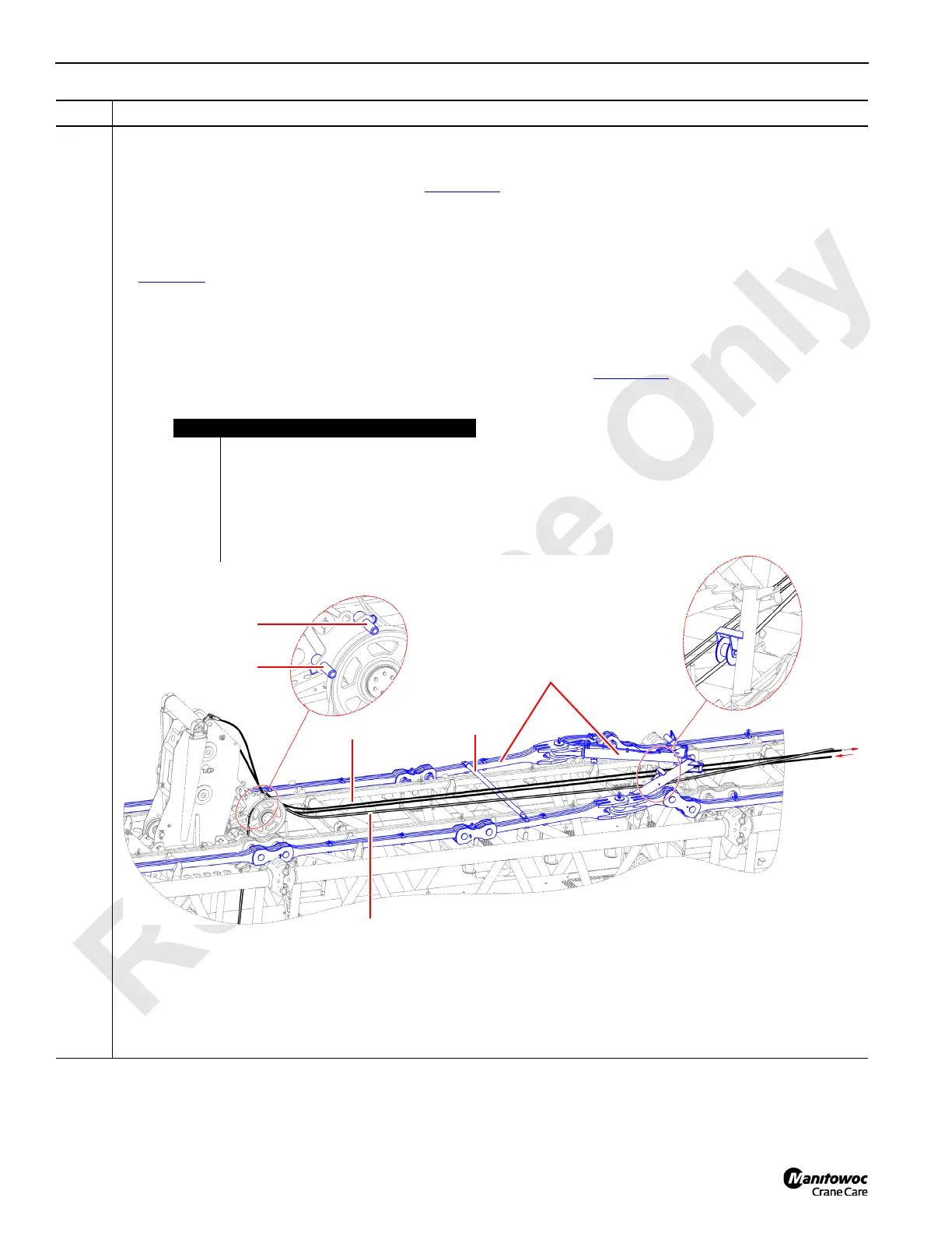
Information below from drawing A19443, Sheet 14:
Jib backstay spreader connection for boom lengths 70 m (229.7 ft) and greater:
• Jib backstay straps shall be connected (see Figure 4-24
).
• Place the jib backstay spreader (A) on the boom insert closest to the last connected jib backstay strap.
• Position the Drum 5 wire rope (B) and Drum 6 winch wire rope (C) under the jib backstay spreader (A).
• The Drum 6 winch wire rope (C) shall also be located on the left side of the top wire rope guide (see A in
Figure 4-6
).
• The jib backstay spreader roller (E) should rest on top of the Drum 5 wire rope (C).
• Remove the jib backstay spreader tie rod (G).
• Both wire rope guards (D) should be in the working position as shown below.
• Attach the jib backstay spreader (A) to the jib backstay straps (F) (see Figure 4-24
).
Step Action
FIGURE 4-26
Spreader assembly connection for cranes with boom lengths 70 m (229.7 ft) and greater
70 m (229.7 ft) boom length configuration shown above.
Item Description
A Jib backstay spreader.
B Drum 5 wire rope.
C Drum 6 winch wire rope.
D Wire rope guard.
E Jib backstay spreader roller.
F Jib backstay strap.
G Jib backstay spreader tie rod.
A
B
C
F
F
F
F
F
F
G
D (lower)
E
D (upper)

 Loading...


