SET-UP AND INSTALLATION 31000 LUFFING JIB OPERATOR MANUAL
4-28 Published 07-23-15, Control # 078-03
28
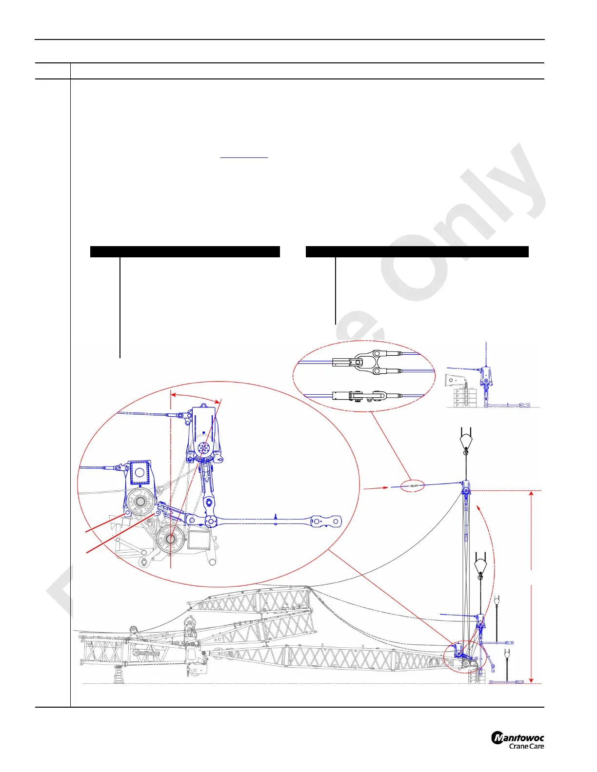
Information below from drawing A19443, Sheet 15:
• Attach the lifting lug (E) on the strut raising pendant (D) to the Drum 1 or Drum 2 wire rope (F).
• Remove the rear strut cap pins (G). These pins will be used in a later step to fasten the strut cap (B) to the top of
the main strut transition insert (H). Leave the front strut cap pins (N) in place.
• Using an assist crane (A), lift the strut cap (B) so that the front strut cap pins (N) disengage from the slotted
holes on the strut cap (B) — see Figure 4-30
for details. Keep the Drum or Drum 2 wire rope slack during this
step.
• Using a second assist crane (L), attach the appropriate backstay straps (O) to the strut cap (B). If a second
assist crane is not available, then lower the strut cap (B) to the backstay straps (O) positioned on the ground.
• While moving toward the top end of the strut cap, lift the strut cap (B) to a height of 41 m (135 ft). Keep the
maximum lift angle (I) less than 20 degrees from vertical. The goal is to be near 20 degrees when the strut cap
(B) is lifted to eliminate the straps and links from contacting the struts.
Step Action
FIGURE 4-29
Item Description
A Assist crane #1.
B Strut cap.
C 2-point chain sling.
D Strut raising pendant.
E Lifting lug.
F Drum 1 or Drum 2 wire rope.
G Rear strut cap pin.
H Main strut transition insert.
I Maximum lift angle — 20° from vertical.
A
A
D
E
F
D
E
F
F
D
D
H
I
B
70 m (229.7 ft) boom length configuration shown.
J
G
N
L
L
D
M
Item Description
J #491 strut assembly top.
K 41 m (135 feet).
L Assist crane #2.
M Backstay strap attachment with one assist crane.
N Front strut cap pin.
O Backstay strap.
O
O
O
O
K