SET-UP AND INSTALLATION 31000 LUFFING JIB OPERATOR MANUAL
4-48 Published 07-23-15, Control # 078-03
50
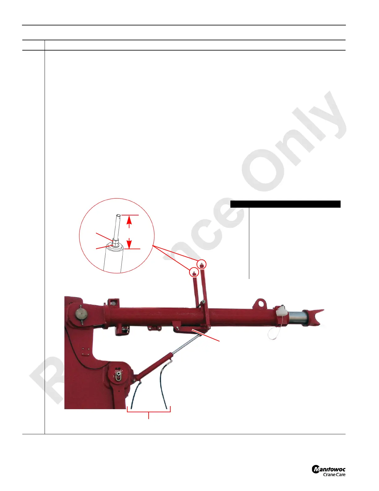
Information below from drawing 81012709:
Set the spring assembly (A) rod guide distance (B) on each jib stop assembly (C) to approximately 117.0 mm (4.61
in):
• The link (D) shall contact the jib stop assembly (C). Use the extend (G) and retract (H) hydraulic lines to move
the link (D) into position.
• Loosen the jamb nut (E) on the spring assembly (A).
• Adjust the nut against the flat washer (F) until the rod guide distance (B) is approximately 117.0 mm (4.61 in)
from the top of the spring assembly (A).
• Tighten the jamb nut (E).
NOTE: After setting the rod guide distance (B), the spring assemblies (A) are now in tension.
Before removing the spring assemblies (A), tension shall be relieved from the rod guides by decreasing
the rod guide distance (B).
• Connect the Arctic 15 hydraulic circuit on the Portable Power Unit (J) to the extend (G) and retract (H) hydraulic
lines. Then fully extend each hydraulic cylinder (I) as shown below.
• After fully extending the hydraulic cylinders (I), disconnect the Portable Power Unit (J) from each hydraulic
cylinder (I). Then position both hydraulic lines (G, H) out of the way for the upcoming jib butt assembly.
Step Action
FIGURE 4-50
Item Description
A Spring assembly.
B Rod guide distance.
C Jib stop assembly.
D Link.
E Jamb nut.
F Nut against the flat washer.
G Extend hydraulic line.
H Retract hydraulic line.
I Hydraulic cylinder.
J Portable Power Unit connections.
A
A
C
D
G
H
B
E
F
I
J

 Loading...


